• Please review our updated Terms and Rules here

IBM 5170 6mhz board won't boot.. "dead"

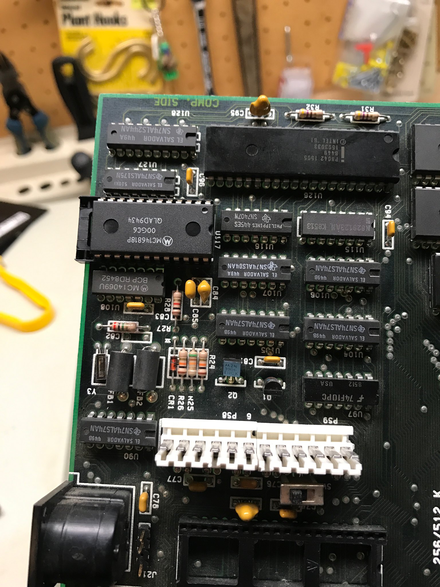
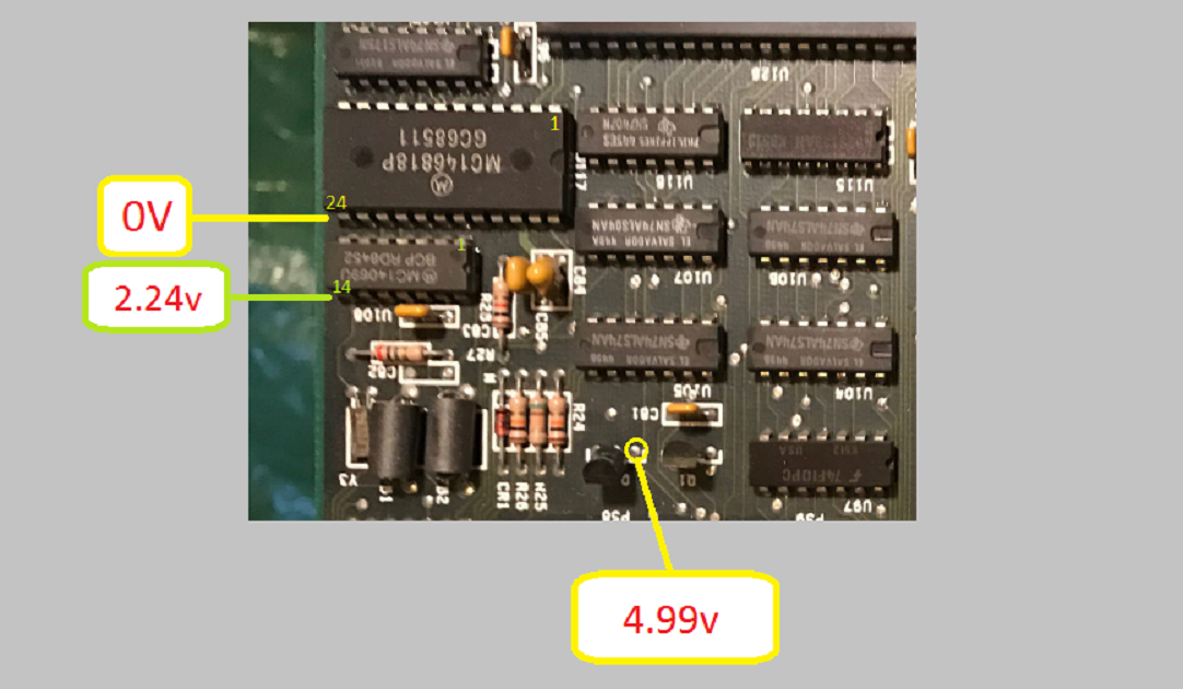
OK, here's what I've tested and the voltages. I put the pin numbers on the IC's in this pic to make sure I have it right, haha. Correct me if I have the pins wrong.

Anyway, pin 28 on U117 reads 0v when board powered on.
Pin 14 on U108 reads 2.5v when board powered on and battery disconnected.
Collector of Q2 reads 5v (That would be the pin on the right towards Q1 shown in the picture above)

31423324403_b4a2decba7_o_d.png
 
5v on Q2 collector is good news, but the pins you checked on the two chips are incorrect.

Check the datasheets on those two chips.... pin 24 on U117 is directly across from Pin 1
And Pin 14 on U108 is directly across from Pin 1 . Pin numbering runs in a 'U' shape.
 
5v on Q2 collector is good news, but the pins you checked on the two chips are incorrect.

Check the datasheets on those two chips.... pin 24 on U117 is directly across from Pin 1
And Pin 14 on U108 is directly across from Pin 1 . Pin numbering runs in a 'U' shape.

Ugh, must have read some bunk information. Boy do I feel dumb, providing wrong information. At least we got that sorted out.

Anyway, the pins check out OK, both have 5v on both of the chips.
 
Hey, don't worry about it, at least now we know the +5 supply voltages are okay on those two chips !
This is all a learning game..... :)

It would be a good idea to check the OSC (blue) line in the diagram Pin 10 on U108.....if you have a scope or logic probe.
 
It would be a good idea to check the OSC (blue) line in the diagram Pin 10 on U108.....if you have a scope or logic probe.
Using a DC voltmeter, that pin measures about 2.3V on my motherboard (with the 2.3V being the average of the clock signal swinging between approx. 0V and approx. 5V).
 
Last edited:
On the MC146818, the pins to check (motherboard powered on) are:

-----------------------------------------
PIN 24 - VDD (power)

So, you have just concluded that pin 24 is in fact getting +5V via the switch.

-----------------------------------------
PIN 13 - CHIP ENABLE (active low)

This pin should be at about 0V. (I.e. chip is enabled.)
Looking at the photo in post #41, you have already measured that pin (incorrectly labelled "24") as 0V.

-----------------------------------------
PIN 18 - RESET (active low)

This pin should be at about +5V. (I.e. the chip not being held in a reset state.)

Is it about +5V ?

-----------------------------------------
Yup, pin 18 is 4.9v
 
There are other inputs to the MC146818, but they are not static - a multimeter is not good enough.
At this point, tools such as logic state analysers and logic probes are required.

Of course, you could always take a punt and replace the MC146818 with new (IC socket recommended). That's easy for me to say; I have spares, sockets, and soldering skill.

I have a oscilloscope I bought at a garage sale for $1, but I don't know how to even use one, so that's out.

I actually am going to just replace the MC146818 chip. Fingers crossed! Now I just need a goat to sacrifice.
 
If you can find a working Dallas RTC chip (e.g. DS1287), one can usually substitute that for the MC146818 and eliminate a bunch of potential problems in the support circuitry.
 
If you can find a working Dallas RTC chip (e.g. DS1287), one can usually substitute that for the MC146818 and eliminate a bunch of potential problems in the support circuitry.

Interesting. I suppose you mean by "working" the battery in the chip needs to be good?
 
Yes, that's the idea, though I suspect even a dead-battery DS1287 will enable your machine to get past the CMOS issues when powered up. Consider that the chip eliminates the issues of the oscillator crystal and battery backup circuitry, as well as the CMOS clock chip itself.

Your basic "shotgun" approach.
 
Is a DS1287 a direct replacement for the existing MC146818 chip ? If so then adding a socket when you remove the
MC146818 chip will allow you to plug in either one.
 
I see that that covers the DS12887, not the DS1287. The DS1287 would have been out-of-production.

By my reading of the referenced document and the MC146818 datasheet and the DS12887 datasheet:

MC146818

According to the Motorola MC146818 datasheet that I have, the MC146818 has a "MOTEL" circuit that automatically caters for the MC146818 being placed in circuitry that uses "Motorola type MPU signals" or in circuitry that uses "Competitor type MPU signals". Per the datasheet, the "Competitor" is Intel.

DS12887

The datasheet for the DS12887 indicates that the DS12887 has no equivalent circuit (maybe Motorola patented it), and consequently, the DS12887 needs to be informed of which MPU signalling is being sent to it. It gets that information via pin 1 (which is an unused pin on the MC146818).

Pin 1 of the IBM AT's MC146818 socket is not connected to anything (I just now checked on my type 1 and type 3 motherboards).

However, a pin 1 related statement in the DS12887 datasheet is, "When connected to GND or left disconnected, Intel bus timing is selected. The pin has an internal pulldown resistance of approximately 20K." So the unconnected pin 1 of the IBM AT's MC146818 socket should not be an issue.

BTW: I see that the DS1287, the earlier chip, also uses pin 1 in the same way.
 
I ordered a spare chip just in case it was the RTC chip in here that was bad.
I just replaced it, and I think we're making progress!

The sockets I have lying around are 4 pins too big, so I ripped some of the pins out and soldered it to the board. I put the new chip in the socket. (picture 1)

I then ran Supersoft ROMS and I'm still getting some memory errors??? (picture 2)

However, after fiddling with the motherboard, I got it to boot with the IBM roms! I moved the jumper back to the 512k position, but the motherboard only counts 256k?? Do I have to set the base memory with the diagnostic disk? I would have thought the motherboard would know 512k when setting the jumper. (picture 3)


31452957694_40982b1570_k_d.jpg

32144465232_679caa3569_k_d.jpg

32145267892_0ecf1540aa_z_d.jpg
 
Really, if you're going to replace sockets, just get some of this stuff:

s-l500.jpg


Cheap, gold-plated, machine-pin. Just snap off what you need--and it leaves the space between the pin rows open. Search ebay for "round female pin header". That way, you ditch the dodgy sockets with no need to keep a bunch of different sizes.
 
Also I tried plugging in a Fixed Disk AT card, and the system wouldn't boot. Probably a short. I measured the resistance on the capacitor at C46 and it's measures 0. The other two caps to the left and right are the same 22uf and they don't measure 0 and make my meter beep.

Why is that cap like a hard black plastic? Could I just replace with an electrolytic axial 22uf capacitor?
31484308373_2f9909dec1_k_d.jpg
 
Back
Top