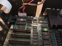
Hello. I am longtime computer tech head and recently came into a mostly original very early model rev A 5150 (s/n below 105000) with the 16-64kb board I am trying to return to original. It did not have original SS 5.25 FD drive and it had an updated U33 BIOS chip which I managed to bend/break the pins pulling out (embarassing) when attempting to figure out why I wasn't seemingly getting power which brought me here.
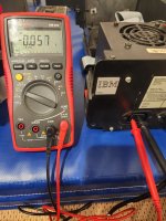
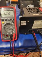
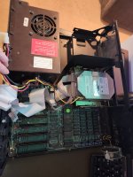
I stripped it down to the minimal config -- original 1981 PSU with the raised nuts (fan spinning), motherboard and speaker but not getting any beeps. I tested the voltages with the P8 and P9 plugged in to the motherboard and everything matching the -0 degrees website working range. +5v +5 +5 -5 +12 -12
Id like to get something on screen but only have a 5151 monitor which will not work with the original CGA card -- first question is what kind of screen could I hook up to the RCA output? Unit has a 1501985 Black and White Parallel card -- what simple type of display will work on this? 5151?
Second question is now that I broke the bios chip and I most likely will not find the original 5700051 anytime soon, where can I get a replica/programmed chip replica replacement? Is it recommended to buy the Landmark Diagnostic chip?
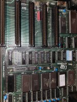
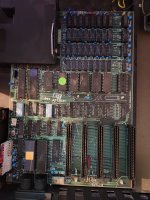
Then to figure out how to get the minimal configuration to give me a sign of life or beeps. I am following the dead 5150 walk through on -0 degrees but not sure how to get measurements on the memory bank blue tantalums as the legs are almost inaccessible to my voltage tester.
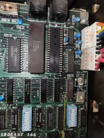
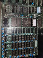
There is a chip labeled C8087-2 populated in the space next to the 8088 '78 chip.
Could the settings of SW1 or SW2 have have something to do with this?
Any ideas much appreciated.
I stripped it down to the minimal config -- original 1981 PSU with the raised nuts (fan spinning), motherboard and speaker but not getting any beeps. I tested the voltages with the P8 and P9 plugged in to the motherboard and everything matching the -0 degrees website working range. +5v +5 +5 -5 +12 -12
Id like to get something on screen but only have a 5151 monitor which will not work with the original CGA card -- first question is what kind of screen could I hook up to the RCA output? Unit has a 1501985 Black and White Parallel card -- what simple type of display will work on this? 5151?
Second question is now that I broke the bios chip and I most likely will not find the original 5700051 anytime soon, where can I get a replica/programmed chip replica replacement? Is it recommended to buy the Landmark Diagnostic chip?
Then to figure out how to get the minimal configuration to give me a sign of life or beeps. I am following the dead 5150 walk through on -0 degrees but not sure how to get measurements on the memory bank blue tantalums as the legs are almost inaccessible to my voltage tester.
There is a chip labeled C8087-2 populated in the space next to the 8088 '78 chip.
Could the settings of SW1 or SW2 have have something to do with this?
Any ideas much appreciated.
")