• Please review our updated Terms and Rules here

IBM Rev A 5150 dead - assistance needed!

Definitely worth a trip if you can find one. Until I started my latest trend on IBM 5150’s I had mostly been working on ver late 80’s and early 90’s Macintosh machines, they mostly used surface mounted chips and SMD capacitors, so I mostly used my hot air workstation, thru hole components were mainly for the Power Supply. I was very rusty, and again these boards are thick and love to disperse the heat from an iron.

But don’t give up, stick with it, you will figure it out. More than likely it will be Something in the lines of U8, U12, U13 or U14, as long as you have a good clock frequency from the clock generator. These data lines are critical to the BIOS and Bus. Again it is not guaranteed these specific chips are the issue which is why Modem7 will tell you that you need to run IO Ready test, to make sure these chips are showing the proper high and low signals. These are Logic Gate Chips. Think of them as Water Faucets, but can flow in both directions. If they get stuck in high or low or vice vera, it will cause the CPU to halt the system (it is a little more technical). I would also download the IBM 5150 Technical Manual, it has a lot of great information, look at the schematics involving the BIOS. I would also look up reading schematics on YouTube, it will help you understand how to read them, so you can understand what pins on a specific chip should be high or low. It helped me figure out one of my MB’s I was struggling to fix.

I appreciate the vote of confidence. I'm ordering the oscilloscope today and heading up to the sticks in Vermont for the 5 day weekend, that lake life. I'll use some of the time to watch some videos on how to use it and come back ready to take this thing further!
 
I'm ordering the oscilloscope today
Perhaps you should watch those videos before you purchase.

My guess is that you are getting some kind of base level oscilloscope. I suggest that you get one with at least two channels. Why? If TEST5066 at [here] needs to be executed, you would be comparing the channel 1 signal to the channel 2 signal, verifying that the two signals are not identical.

m7 just circling back around -- I realize the oscilloscopes are quite pricey and under normal circumstances I am not a cheapskate and would be more open to spending $200-$300+ (still seemingly on the cheap side for these) but the reality is my 5150 budget is extremely tight at the moment.

I found the following and wondering if based on specs it appears to be able to provide the readings (10mhz bandwidth?) I will be going after? I'm really trying to stay under $200.

 
m7 just circling back around -- I realize the oscilloscopes are quite pricey and under normal circumstances I am not a cheapskate and would be more open to spending $200-$300+ (still seemingly on the cheap side for these) but the reality is my 5150 budget is extremely tight at the moment.
I understand. Now that I am retired, the money flow is much less.

I found the following and wondering if based on specs it appears to be able to provide the readings (10mhz bandwidth?) I will be going after? I'm really trying to stay under $200.

10 MHz bandwidth

Something to be aware of is that a non-sinusoidal waveform contains more than one frequency. For the example of a square wave (such as a motherboard clock signal), see figure 2 at [here]. That frequency plot (frequency spectrum) of a 1 Hz square wave shows the 1 Hz 'fundamental' frequency plus all odd harmonic frequencies, in a descending amplitude.

So, if one wants an accurate measurement of a square wave, the bandwidth of the measuring device needs to include a significant number of harmonics. The less included harmonics, the less accurate the measurement.

The top row of comparison photos at [here] show the effect of measuring a 4.77 MHz clock signal using an oscilloscope that has a 10 MHz bandwidth. 100 MHz on the left, 10 MHz on the right.

And per [here], going to a 20 MHz bandwidth oscilloscope doesn't make much difference.

And those diagrams shows that 10 MHz bandwidth is adequate for thing like the signal leaving pin 13 of the 8253 timer.

Back to the 4.77 MHz clock signal. At least the 10 MHz bandwidth is showing something present; it provides a certain amount of confidence. And if things like the 8253 pin 13 signal are seen (i.e. the initial source is the 4.77 MHz clock), then you can deduce that the 4.77 MHz clock signal must be good.

Other

As I wrote earlier, two channels for things like TEST5066. And for measurements like [here].

As something that will assist in IBM 51xx diagnosis, it will do the job.
 
OK. So I ended up with a Rigol DS 1102Z-E 2 channel 100 mhz Oscilloscope. Wife asking me how much longer my setup is going to be here. 2 more weeks...honey.

Looking forward to the 4.77mhz and 8253 chip tests and getting closer to figuring out what is going on here. I've been watching a few 5150 vids of Adrian's Digital Basement on Youtube and while he is real good, I hope I am not going over my head here but we are going to give it a shot.

Any 5150 specialists in the New York New Jersey area please feel free to dm me!

Til next time.
 
Looking forward to the 4.77mhz and 8253 chip tests and getting closer to figuring out what is going on here. I've been watching a few 5150 vids of Adrian's Digital Basement on Youtube and while he is real good, I hope I am not going over my head here but we are going to give it a shot.
Online videos may lead to a fix, but there will be many cases where they will not.

A computer technician will do some basics. Then, just like a doctor, will make initial measurements, and based on those (and knowledge of how the computer works), lead to a different set of measurements, and based on those, lead to a different set of measurements, and so on. Homing in on the problem cause in a logical diagnostic manner. Eventually, the problem cause is found, done so logically.

Looking back through the posts, you have voltages, you have re-seated chips, done a close visual inspection, obtained replacement ROM's, but still no joy. Confidence that a proper CPU reset is happening. So far, no evidence of U33 ROM code being executed (step 10 at [here].)

Now that you have an oscilloscope, you are in a position to try the first 9 steps of the procedure at [here], which is simply seeing if the first byte of the reset vector in the U33 ROM is being correctly read and getting to the CPU. The particular result (all 9 steps as expected, or fail at step X) dictates the diagnostic path then taken. A logic probe is the best tool to use in that procedure, but an oscilloscope is fine.

Possible tools needed later:
- EPROM programmer and suitable EPROM's (possibly an adapter) as well. To create ROM's containing custom diagnostic code/data.
- The device pictured at [here]. Used as the output device for some custom diagnostic code. Very cheap.
 
No beep on start running minimal diagnostic config. No visual issues, PSU tested good, All RAM removed, 8087 removed, switches correct --> confirmed no mb short, 4.77hz confirmed, 8088 pin 19 received, reset low good. I am not seeing the U34 chip mentioned above showing pin 13 pulse (testing with computer running, not during startup -- does this matter?).

Reviewing, I was thinking my next step would be to start the GROUND IO CHK READY steps 1-13 -- and sure enough as I read your response and follow your reference from post 26, that's exactly where we left off.

To get me going, I am a little stuck and confused regarding the grounding procedure. The page says to ground to the expansion slot pin A10 but I am not sure how to do that? Can someone lead me to a visual of this in action? Do I need to run a ground wire from A10 to the oscilloscope ground probe via alligator clip?
The single observation of no pulses (pulses of expected duration and frequency) on pin 13 of the 8253 simply informs you that either:
- The POST is not starting; or
- The POST is starting, but not getting as far as the step that programs the 8253 to output the required pulses on pin 13; or
- Faulty 8253.

Yes, the 'ground I/O CH RDY' procedure is appropriate at this time, informing you if the motherboard is even getting to the point of starting the POST.

To get me going, I am a little stuck and confused regarding the grounding procedure. The page says to ground to the expansion slot pin A10 but I am not sure how to do that? Can someone lead me to a visual of this in action? Do I need to run a ground wire from A10 to the oscilloscope ground probe via alligator clip?
At step 2, I point to a photo of what I use.

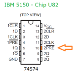
As written in step 2, one end goes to either pin A10 of an ISA slot, or to pin 10 of chip U82.

The other end can go to any ground on the motherboard.

I typically use U82 for both, i.e. one end to pin 10 of chip U82, and the other end to the ground pin of U82.

1729206871608.png
 
Back
Top