• Please review our updated Terms and Rules here

In search of good clean power

Mike_Z

Veteran Member
Joined
Dec 1, 2013
Messages
1,713
Location
Near Milwaukee Wisconsin
I've been working on a home built 8080A computer, that I made in 1976. Sometimes it works like a camp and other times it will frustrate me to no end. The computer is a s-100 based machine. I have a section of an old IMASI mother board for my S-100 bus. I have 5 vector wire wrap boards on the bus, each with a local +5 volt regulator (7805). I have made some improvements to the main power +8 system. I have added an adjustable switching regulator to lower the general +8 volts from around +11 to a little over +8. This relieves the 7805 some and they run a lot cooler. The ripple on the main power is about 0.1 volts or less. With all the board in service I am drawing about 5 amperes.

The problem is noise on the individual boards. I have replace all the 7805 regulators, they all have heat sinks and have heat transfer paste on them. I have measured the heat sink temperature and the hottest one is about 120 degrees F. Each regulator has a 0.47 uf capacitor on the input and a 0.1 uf capacitor on the output. Each of these capacitors are mounted right at the terminals of the regulator. These capacitors are ceramic type. I've also installed a number of 0.01 uf ceramic caps near most of the IC's. Generally this solves the problem of noise on control lines etc.

Yet, this last week I have been chasing noise on my CPU board. The noise has been getting on my RESETIN line causing the CPU to lose it's focus. Today I'm going to change the 7805 again, with a new one. and maybe add a few more bypass caps. I've been reading about proper bypass but need more help. Any suggestions would be appreciated.

Thanks
Mike
 
There are all sorts of things you can do. Use twisted-pair for your interconnect signal lines; make sure that longer lines are properly terminated; Connect grounds between boards with heavier cable, make multiple ground connections, use common grounding points to avoid ground loops. If it's just a single signal or two, try using Schmitt triggers as receivers (sometimes this can simply be done by replacing a 74LS04 with a74LS14). Power connections should be of a gauge and length appropriate; use ferrite inductors/beads for high-frequency noise removal. Use adequate decoupling caps after each regulator.

The list is very long.
 
I've been repairing one of my Ithaca DPS-1 S100 computers for the past few weekends. Some days I could get small hand loaded routines to output to the serial port other days not. I also had the disk drive attempt to boot one day, and then nothing after that. After probing and trying to isolate these random events, I got desperate and tried cleaning the S100 connectors on all the boards. Works like a champ now, no more intermittent problems. I chalked this one as lesson learned, "Clean the connectors as part of the initial power supply check!" then see what works and what does not.

Kipp
 
.. Each regulator has a 0.47 uf capacitor on the input and a 0.1 uf capacitor on the output. Each of these capacitors are mounted right at the terminals of the regulator. These capacitors are ceramic type. I've also installed a number of 0.01 uf ceramic caps near most of the IC's.

Your reg output cap of 0.1uF seems undersized?
 
No, that's what's recommended in the LM7805 datasheet. The idea is to provide enough bypass to keep the 78xx from oscillating, but otherwise leave the regulation active. A big cap on the line side, however is quite desirable. A big one on the load side will actually impede good regulation.
 
No, that's what's recommended in the LM7805 datasheet. The idea is to provide enough bypass to keep the 78xx from oscillating, but otherwise leave the regulation active. A big cap on the line side, however is quite desirable. A big one on the load side will actually impede good regulation.

This.

Generally speaking, you don't want much more than about 22uF on the output of a linear regulator like the 7805. One will often see a moderate value film cap, like something between 0.2uF and 1.0uF.
 
Well, yesterday I thought I found the problem, but it didn't change the machines behavior. I found a open input on a 74ls367 buffer. (I made a circuit change a few months ago and forgot this one) This open input caused the noise on the reset line. After grounding this unused buffer the noise was greatly reduced. The machine is still stubborn and I need for more investigation.

This brings up a construction practice question regarding unused inputs. I know that an open input can sing to beat the band, I always wondered whether it is best to ground or pull high unused inputs? So I set up a 7404 chip and measured the total current draw on the power pin, when all the inputs were high and low. I had speculated that grounding the inputs would cause the chip to draw more current (TTL chips), but my experiment shows that with the inputs high, the chip draw more current.

I also have resolved the power problem, but again for some reason, my front panel switches are not working correctly. I can boot up my monitor program and everything is fine (front panel is disabled when this program runs). More looking

Mike
 
Re: Whether or not to ground or pull up (through a resistor, please) unused inputs, depends to a large extent on the chip. On totem-pole output chips, one transistor or the other on the output is going to be activated, so the question goes back to whatever else is in the chip. If you're going to pull an input high, however, use a resistor--do not connect it directly to Vcc.

And never leave CMOS inputs floating. That can actually damage the chip by causing both output transistors to turn on.
 
A big one on the load side will actually impede good regulation.
How is that? :confused: A larger cap on the load side can't effect the DC parameters. It will only improve the AC parameters of output noise, transient response, output impedance, ripple rejection.
 
Not so--recall that a 78xx regulator is a series-pass regulator--it can pass more or less current, but it cannot be a current sink. A large cap on the output prevents the 78xx from responding rapidly to load conditions. Somewhere,I recall that there's an old NSC app note that talks about this subject. If you're going to use a cap to reduce ripple, put it on the line side.

Modern switching buck/boost converters are very different in that respect.

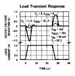
I can't agree. From the National Semiconductor LM78XX datasheet: "It is not necessary to bypass the output, although this does improve transient response." The problem is that the 78xx cannot respond fast enough on its own to a fast change in output current (which I assume is what you mean by responding rapidly to load conditions). The output capacitor sources or sinks the current spike until the the regulator eventually responds. Consequently it improves the response to a changing load.

The LM150 datasheet, which is also series-pass, has a plot showing this:
Transient Response.jpg

Archive.org has a copy of the old National Semiconductor Voltage Regulator Handbook with lots of app notes and datasheets.
 
It struck me that you might be remembering an app note that says that a large output capacitor can possibly damage the regulator if the input voltage goes rapidly to zero. Since the regulator can't sink current, the output voltage will be held higher than the input by the capacitor, which could damage the regulator. The app note suggests putting an external protection diode from output to input to prevent this problem.
 
I'm no expert, but can speak from experience. The 0.1 uf output capacitor definitely improves performance. Without it I see noise on the output most times.

Mike
 
You prompted me to do some homework--with the result that I received little satisfaction in a definitive answer either way. :rolleyes:

Among the more interesting statements I read were:

  • Running a 78xx regulator is perfectly fine without any output capacitor because the 78xx has a zero-gain emitter-follower output and so cannot oscillate. The same is not true for the 79xx regulator.
  • Putting a large capacitance (~~ 100 uF) on the load side is fine, so long as it's not a low ESR capacitor.
  • Putting a large capacitance (~~ 100 uF) on the load side is fine, but it has to be a low ESR capacitor.
  • With capacitors > 100 uF on the low side, you must add a high-current diode to bypass the regulator should the supply fail short--the reverse current flow could take out the regulator otherwise.
  • If you're going to spend money on capacitors, put them on the line side.
  • None of this really matters much--follow your heart.

Take your pick.

As far as ripple rejection, that shouldn't be too much of an issue--the datasheet says that the 7805 has ripple rejection in the range of 40-50 dB, which should be more than adequate.

Midst all of this, the only solid conclusion I can come to is that the 0.1 uF capacitor on the input and output sides is a very good idea, particularly if traces or PSU leads are long--and the cap should be there, regardless of any additional load capacitance hung on the line.

Beyond that, my reaction is <shrug>. Let better people with time on their hands argue the fine points.
 
Chuck, I've been looking over my circuits and have found that I indeed have a bunch of TTL inputs pulled high directly to VCC. In some cases, I can reconnect these inputs to other used inputs such as a 4 input NAND where only three inputs are being used. Obviously, on any completely unused gates those inputs will be grounded. BUT, what about inputs like CLEAR or secondary latch inputs on latches and Flip Flops that I may have pulled HIGH, I have all of those tied directly to VCC. Should I pull these high with a resistor?

I have read that pulling an unused input can cause input emitter damage should a transient voltage appear, > 5.5 volts, on multiple input devices. Does this go for devices like 74123's where there are two clears?

Mike
 
It struck me that you might be remembering an app note that says that a large output capacitor can possibly damage the regulator if the input voltage goes rapidly to zero. Since the regulator can't sink current, the output voltage will be held higher than the input by the capacitor, which could damage the regulator. The app note suggests putting an external protection diode from output to input to prevent this problem.

Irrespective of the capacitance on the output side, using a protection diode (1N400X is fine) from output -> input (band to input) is never a bad idea. And the parts are so cheap, there's really no excuse not to put one in. Think accidentally crossing +5V and +12V supplies..
 
I've been reading some. I found on an TI document that if an input is to be pulled high, it should be thru a resistor. Apparently a transient of over 5.5 volts can damage TTL device especially those with multi emitter inputs. The pull up resistor basically limits current. There is no mention of resistor value or if each input needs to have a resistor or if one resistor can be used to pull high more than one chip's input's. I found on a Fairchild document, recommends tying unused inputs thru a 1K (actually 1 to 5K) resistor to VCC. They say that the benefit is less current draw Iih is smaller than Iil and will limit current during surges (those VCC over 5.5v mentioned in the TI doc) They also say that a single 1K resistor can handle up to 10 inputs. This suggests that one resistor can be used for all inputs on a more than one chip.
There is also a lot of stuff about noise, length of conductors, grounding, bypassing, etc. I'll be making some changes in my circuits.
 
Mike, you've got the reasoning--damage to the IC, particularly when you're using the older non-LS TTL logic. I've been doing it for so long, that I don't give it a second thought any more. Part of my usual TTL designs are to provide a couple of resistor network SIPs extra for use as pullups.

On the old non-LS TTL, it's also important to have generous power supply rails to minimize the effect of switching transients on the power supplied to a chip.

As I mentioned, any unused inputs on CMOS logic must be terminated. They're high-impedance and "floating" voltage levels on them can put the IC into a weird and possibly self-damaging state. Some CMOS ICs incorporate weak pullups as part of their fabrication which avoids this situation--but check the datasheet if there are any doubts.
 
Back
Top