peterfleeman
New Member
- Joined
- Feb 13, 2017
- Messages
- 3
I am getting to this party pretty late, but I just acquired an inboard 386/pc card and I would love to experiment with one of these daughter cards. Any chance we could make more?

All, sorry for not seeing these sooner. I put the project on hold when I moved last year and haven't worked on it recently. I have ordered 5 more prototype boards, DM me if you want one.
")

I am about to build mine! I have the exact same CPU configuration for my inboard by the way. I do have a 40 MHz crystal by the way and that works with great stability.I can vouch for the 2mb working great I reached out to Harrison of all places over Reddit after seeing his posts on there.
Looking forward to the larger ram models
Thanks Harrison!
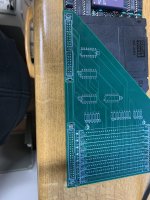
View attachment 1252466
So is there a suggestion to change the oscillator? Not too keen to start desoldering the main card. But I may be tempted. I’ve a few different fpu’s I would like to locate an IIT x2 but not seen one yet.I am about to build mine! I have the exact same CPU configuration for my inboard by the way. I do have a 40 MHz crystal by the way and that works with great stability.
So it isn't the easiest thing to desolder the oscillator - I ended up breaking mine and I even used a desoldering gun. But you just put in a socket and then you can experiment. The 40 MHz oscillator works great and if you are using a clock doubling chip then it is worth 8 MHz of extra performance.So is there a suggestion to change the oscillator? Not too keen to start desoldering the main card. But I may be tempted. I’ve a few different fpu’s I would like to locate an IIT x2 but not seen one yet.
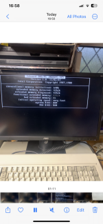
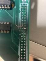
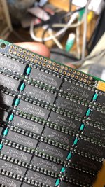
What is the short connection in the last picture for? Is that required to get the 4 MB card running?Anyway onto bigger news with a bit of alteration as advised by Harrison mine seems nice and stable at 4mb! Though there’s 8mb actually sat in the memory slots it maxes out now at 4. I need to perhaps reduce what is in there. Looking forward to the next revision for even more ram access.
You need a steady hand but it’s not too difficult.. (even a ham fisted guy like me managed to solder it)
Yes it’s a change in connectivity from pin 19 to pin 15, also severing the trace to 19. This allows the card to address 4mb in place of 2mbSo it isn't the easiest thing to desolder the oscillator - I ended up breaking mine and I even used a desoldering gun. But you just put in a socket and then you can experiment. The 40 MHz oscillator works great and if you are using a clock doubling chip then it is worth 8 MHz of extra performance.
What is the short connection in the last picture for? Is that required to get the 4 MB card running?
I didn’t know that was needed to enabled 4 mb. Is there a GitHub for this that I am missing? My ram gets here today and I am almost done putting together the card although I accidentally soldered the pin headers on the wrong side so that will be fun to reverse.Yes it’s a change in connectivity from pin 19 to pin 15, also severing the trace to 19. This allows the card to address 4mb in place of 2mb
I asked Harrison directly the initial design supports 2mb natively. The hack I mentioned opens up 4mb, a redesign will have to follow for anything larger as I understand it..
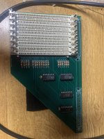
 Almost done. I have to put in the chips but have to look up the right place for the right ones. Anyway, somehow I accidentally bought 8 meg of ram - I thought I was buying 4. Too late to test it tonight. I didn’t do any hack or anything - just built the board. Will it work for 2 meg with the 8 meg chips?
Ugh…. Pin headers don’t fitView attachment 1252755Almost done. I have to put in the chips but have to look up the right place for the right ones. Anyway, somehow I accidentally bought 8 meg of ram - I thought I was buying 4. Too late to test it tonight. I didn’t do any hack or anything - just built the board. Will it work for 2 meg with the 8 meg chips?
Mine had 8mb in ram as I wasn’t sure if the size of what I had available and ran as 2mb initially and further expanded to 4mbView attachment 1252755Almost done. I have to put in the chips but have to look up the right place for the right ones. Anyway, somehow I accidentally bought 8 meg of ram - I thought I was buying 4. Too late to test it tonight. I didn’t do any hack or anything - just built the board. Will it work for 2 meg with the 8 meg chips?
Yeah the tolerances are very low. So it’s why there was advice to solder them in place while connected to the card.M
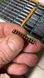
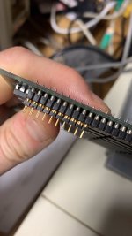
Ugh…. Pin headers don’t fit
can you perhaps remove and resolder?Or are you using standard pin headers?Yeah the tolerances are very low. So it’s why there was advice to solder them in place while connected to the card.
BDL-110-G-F BDL - Samtec 2.54mm Low Profile Double Row, Screw Machine Terminal Strip - Fast StockOr are you using standard pin headers?
You need the machined headers as they are a round hole standard pin headers don’t work for this.. the type are listed on the BOM in this forum.