• Please review our updated Terms and Rules here

Intel C4004 based Prolog card?

It says the attachments are invalid. We are most interested in an edge connector list. There is a schematic in the printer manual for the board but it doesn't list the edge connector pinout,. We have disassembled the two 1302 chips but sadly the first chip has a stuck, high, bit4. I still need to get the disassembler to snuci but wanted to make a few enhancements since his data will have a blank 512 bytes between the last data of the second 1302 and the the 2K byte mask ROM. He has 1702s he can use for the first three EPROM. For the assembler, I need to makes similar changes to write out the 3 or 4 ROMs, he may decide to use. Right now it writes a single large file with no separations. We'd vary much like to see the original Prolog data. I was doing searches and found that it matched the description of the PLS-411, so assumed it would be the same. Without tracing wires I'm not sure about the two unpopulated RAM locations. It looks like to fill these would be a 4002-1 and a 4002-2.
We'd also be interested in any application data these may have been used for.
Dwight
 
Sorry for the delay. Apparently I'm not getting notifications when there is activity on this thread.

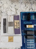
Here are the links to the photos of Pro-Log PLS-401 and PLS-411 cards with their DTC branded versions. I can ohm out the card cage if you like.

Incidentally, I am in search of a power supply for the DTC-300. Mine is inoperable at the moment. Care to sell?

https://remote.flashautomation.com/PL401.jpg
https://remote.flashautomation.com/PL411.jpg
https://remote.flashautomation.com/DTC401.jpg
https://remote.flashautomation.com/DTC411.jpg

Thanks,
Flash
 
Hi Flash,

Thanks for the reply. I don't have any other cards or the original card cage so I only have that one card. I can figure out the pinout when I get some time. I was just hoping it was standardized in some way.

For the DTC-300 power supply, I will check with the original owner if he wants to sell. I'll let you know.

Thanks.

I sent this to your mail. Here is the list for the edge connector:

PLS-411 pin list


1 +5V 2 +5V

3 GND 4 GND

5 -10V 6 -10V

7 OUT 2-8* 8 RAM OUT 8

9 OUT 2-2* 10 RAM OUT 4

11 OUT 2-1* 12 RAM OUT 2

13 OUT 2-4* 14 RAM OUT 1

15 OUT2 1-8* 16 CLK1

17 OUT 1-2* 18 TEST

19 OUT 1-1* 20 OUT 3-8*

21 OUT 1-4* 22 OUT 3-2*

23 OUT 0-8* 24 OUT 3-1*

25 OUT 0-2* 26 OUT 3-4*

27 OUT 0-1* 28 RST* OUT

29 OUT 0-4* 30 RST IN ( -10V )

31 IN 2-8* 32 IN 0-1*

33 IN 0-8* 34 IN 2-2*

35 IN 2-4* 36 IN 0-2*

37 IN 0-8* 38 IN 2-2*

39 40 IN 1-8*

41 42 IN 3-8*

43 44 IN 1-1*

45 46 IN 3-1*

47 48 IN 3-2*

49 50 IN 1-2*

51 52 IN 3-4*

53 54 IN 1-4*

55 56 IN CLK2


The board has no buss, to the edge connector. It is just I/Os for controlling stuff. As for supplies, most linear 12V supplies can be easily modified to 10V with the change of a resistor. If the pass transistor is getting too hot, a power resistor can be added to handle the excess heat, with a series resistor to the regulator transistor. It can be done with a parallel resistor but that has the danger of over voltage with light loads.
Do be careful with dual supplies that are +5V and +12V. Most of these can not easily separate the return leads for the +5 and +12. Some are made as two isolated supplies. This is the type you want. You can then connect the +12 lead to the return of the +5, giving you a negative rail.
There are a number of unused pins on the board's edge connector that could be use to do things like pass out more RAM output pins ( PMOS levels ) or other such things.
Dwight
 
Back
Top