• Please review our updated Terms and Rules here

Interest in I4004

Dwight Elvey

Veteran Member
Joined
Jun 21, 2003
Messages
4,995
Location
Santa Cruz
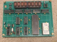
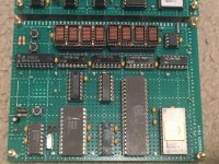
I'm posting this to maybe stir up some interest in the I4004. This is some code I wrote for my MCS-4 setup. It is complete with the SIM4-01 and MP7 1702A programmer. Normally I use it to read and/or program 1702As. I wrote this program to speed up the programming of multiple EPROMs. Because the normal code that is used with this setup is normally fed from a paper tape at 110 baud and in BNPF format, it takes 7 minutes to program a 1702A. The data sheet says you can program a 1702A in 2 minutes. The extra 5 minutes is used to down load the data at 110 baud. When programming multiple EPROMs with the same code, it would be great to copy them and do it in the 2 minutes.
This is 4004 code to do just that. It is not in standard Intel format but if you know 4004 code, I'm sure you can figure it out. It is an assembler I wrote for the 4004. I is a single pass assembler so forward references are a little different. Other than that and the fact that the instruction in in RPN, it should still be readable.
The file is a Forth source but I've changed the extension to .txt from .f so that it can be posted here ( also easier to view ).
If you have a I4004 program that you've written, either for a 4004 machine you have or one of the simulators, you might post it here. That is the intend of my posting it here.
Even if your not going to post a 4004 program you might have fun trying to understand the peculiar 4004 instructions. Bitsavers has a number of resources to look at for the 4004 instruction set.
Dwight

View attachment ONECOPY.txt
 
Hi Dwight,

What is your MSC-4 setup? and Intellect 4?

At some point I'd like to put together something with my box of 4004 family chips. At the 4004.com site I see a reference to a single board 4004 trainer. Except for the 4003's I have pretty much everything. (http://www.4004.com/busicom-replica.html) It would be cool to have something running.

len

This is a picture of my machine. It was taken a number of years ago at Stan Seeler's (sp?). There are LEDs for most every thing. There is a serial connector. The board in front emulates a 4001 ports, both input and/or output.There are two 4002-1 and two 4002-2. It was intended to be used to breadboard an application. The board in back programs 1702 and 1702A chips, with the firmware you see in the picture ( 1702s require the third IC to have different code, mostly different delays ). The code I wrote runs in the first socket to the left ( doesn't need the other two but no need to remove them ). 4 of the LEDs are used to keep track of what operation, Master, EPROM, Master EPROM when doing the copy.
Dwight

4004sm.jpg
 

There are a couple of applications that is in the archives of the NPG school in Monterey,Ca. It is used to calculate the maximum weight your helicopter can take off with. It would most likely run on your machine with some modification to the I/O.
There is also an other that is a calculator for closest point of approach. This would be used for ships. You'd enter the vector and range of other ships. I think it can handle 5 ships This is important, not only to avoid hitting them but also, knowing when a possible target would be in range. I suspect you'd need to increase your ROM space to do that one.
Both are PDFs of printout done on a ASR33 with poor registration, meaning 0 sometimes look like C. It would be great to get either working as these are real world applications.
I've been meaning to put together a 4040 setup using a 4289 ( think that's right ) and a number of 4265's. These only work right with the 4040 but they are really flexible I/O chips.
I have the two PDFs someplace if anyone is interested.
Dwight
 
I've been meaning to put together a 4040 setup using a 4289 ( think that's right ) and a number of 4265's. These only work right with the 4040 but they are really flexible I/O chips.
I have the two PDFs someplace if anyone is interested.
Dwight

Yes, please post the pdfs!

len
 
This is a picture of my machine. It was taken a number of years ago at Stan Seeler's (sp?). There are LEDs for most every thing. There is a serial connector. The board in front emulates a 4001 ports, both input and/or output.There are two 4002-1 and two 4002-2. It was intended to be used to breadboard an application. The board in back programs 1702 and 1702A chips, with the firmware you see in the picture ( 1702s require the third IC to have different code, mostly different delays ). The code I wrote runs in the first socket to the left ( doesn't need the other two but no need to remove them ). 4 of the LEDs are used to keep track of what operation, Master, EPROM, Master EPROM when doing the copy.
Dwight

View attachment 44141

Did you design/build that, or was it commercially made? Do you have a larger image?

Thanks

len
 
This was an Intel product before the MOD4. They gave many of these away to various companies with hopes that they'd create products. I suspect they eventually charged for these but all the stories of these indicate that they were handed out free. I got this one 3rd or 4th hand. The entire unit is described in the MCS-4 manual found on bitsavers.
It came with the code described as A0540/1/3 that is the code to run the MP7 board to program 1702As. The code for A0542 is combined with A0541 and A0542 to be for 1702 (non-A). These require shorter pulses and more delay between pulse. Programming time for the 1702 is 20 minutes while the 1702A is 2 minute.
There is one other piece of code mentioned in the manual, it is the A0740/1/2/3 PROM set. I've been look for this set for a number of years. A friend in Norway finally located a set but I'm afraid the A0743 EPROM has serious bit rot. The other three look to be in good shape. This code is said to be an assembler for the 4004. I've been running what I can on my simulator but without the last EPROM it doesn't get to far. From what I was told by people that worked at Intel at the time, the code was written by Tom Pittman, of Tiny Basic fame. He'd done this in exchange for the setup, like I have. It seems he wrote a mail program that he use for the "Home Brew Computer Club". I've contacted Tom but he says most all of that stuff is lost over the years.
I've not given up on the A0743 EPROM, I'm making a setup that can vary the voltage and threshold to read these. It should be able to pull and residual values out of the EPROMs. Hopefully I can get that little bit of charge to read out.
On the PDF's This was code written by students of Gary Kildall, while he was teaching at the NPS.
One coding, I've found that has another useful instruction. It is the SKIP instruction. It is most useful for causing the execution of with multiple values into a subroutine. It is a JCN instruction that has no condition. Instead of the address, you have a LDM instruction ( or similar ). Say you had a PRINT subroutine, you could precede it with multiple of these skips. Something like
LINEFEED SKIP
LDM $0A
RETURN SKIP
LDM $0D
PRINT ......
This code doesn't make much sense since it is only 4 bit and not 8 but you get the idea.

You'd need to add this instruction to your assembler or do it as a DB.
I was decoding some code on a board the fellow in Norway found and it had a few locations with these SKIPs in it. It didn't make sense at first because it was a JCN without any condition to check. Then I realized it was a clever trick to have a repeated parameter to a subroutine. If you used that parameter more than once it made sense to have the multiple skips at the beginning. It had one subroutine with 5 of these in a row. It is an Always Don't Jump instruction.
The code looked like some key pad entry code ( a typical application for the 4004 ).
I'll dig that code up if interested.
Dwight
 
Last edited:
On the SKIP instruction, how it works, from the manual

JUMP IF
!C1 * ( (ACC==0) * C2 ) * ( (CY==1) * C3 ) * ( !TEST * C4 ) |
C1 * ( (ACC<>0) | !C2 ) * ( (CY==0) | !C3 ) * ( TEST | !C4 )
ENDIF

If C1 is 0 the bottom terms are always 0.
If C2, C3, C4 = 0 then the top term is also 0.
so, the instruction bits 00010000 is a SKIP. It will skip over any 8 bit instruction.

Note my edit!!! Typing too fast without thinking.

A better example:

Code:
USE0    LDM 0
        SKIP
USE1    LDM 1
        SKIP
USE2    LDM 2
         ......   some code to use ACC
Dwight
 
Last edited:
These are the 2 applications that were from Kildall's students. There may have been others but these were the two that I found.

Rather than posting two large pdfs, I don't own, here are two search strings that
will get you the files. Use Google and look for the pdf from Calhoun.

maneuvering board problem kerns calhoun

helicopter flight system microprocessor eloe

Dwight
 
I just went back and made another edit to my SKIP post I forgot a 0.
0001 0000 is a SKIP or for 3 letters SKP
0001 1111 is a short Jump on page. You night call it a JPG. It is not vary useful as a JUN takes the same number of bits.

Another case for skip
Code:
FF2P  LDM $F    ; Write all 1's to port
      SKIP
Z2P   LDM $0   ; write all 0's to port
      WMP

or

A2P   SKIP        ; write ACC to port
Z2P   LDM $0   ; write all 0's to port
      WMP

Dwight
 
Last edited:
Hi All
I thought I'd post an update on a project I started working on. I have been off and on transcribing the listing for the Maneuvering Board program, written by one of Gary Kildall's students. I got more serious about 2 weeks ago and finished my transcribing.
I've been debugging using my own simulator and have finally got the code working. At times, I had the feeling that maybe the listing didn't have totally working code. Unlike a current listing, there was no Hex assembled values, just line number and address in both octal and hex.
I fought many 0s and Cs that looked much alike. Things like F and P were not as big a problem as they were only an issues for labels and not confused with different assembly code.
Anyway, I got the last bug out of the code earlier to day. I expect to start working on a PCB.
I'd been slow at getting things started until recently I found some 4002-2 parts that were relatively cheap. The project needs 4 each of the 4002-2 and 5 of the 4002-1. It has been a while since I've seen 4002-2s for less than $75 each. I just got the last part I need and that is a 4289 chip. I'm not planning on using 4001s as they are mask made and 1702As would still need an interface. I'll be using a 2732 as the code is less than 4K.
I'll have a switch array. It needs 25 buttons ( of course part is 10 number keys ).
It was a good thing that the original pdf had a couple of working examples. As I mentioned before, I expect to use other than the original displays but will leave it open for possible future to make a more complete setup with 16 LEDs for the display.
I had to make enhancements to my simulator. I originally wrote it when working with my SIM4-01 setup. I wrote a 1702A copy program that I could use on the SIM-01. It normally takes 7 minutes to program a 1702A as 5 minutes to down load BPNF data. In now takes all of 2 minutes but does take a little attention as the SIM4-01 only has enough RAM for half of a 1702A.
Any way I'll start my board design soon now that I have working code. It is fun in that on the I4004 it takes about 5 seconds to complete the calculations. On my simulator is responds back as soon as I hit the return. This includes all of the hooks I've got in my simulator for debug assistance.
Dwight
 
Definitely interested, this year FOR SURE I will build a 4004, probably as a wall-mounted clock. One of the PITA aspects of building a small one is the +5/-10V supplies, but I found a nice small DC-DC converter on eBay that can be powered by an orphan laptop power supply. I don't have any 4002-2's but I probably won't need any, I have the -1's; I have a tube of 4289's but I also have a 4008/4009 set (which is really a bit more period correct for the 4004). Hope they work!
 
Having only -1's shouldn't be an issue. You'll just have a breaks in your memory map. As I recall, it goes through the two hardwired addresses first and then the -1/-2 steps. So if you only need 2 RAMs you'll have a continuous memory map.
I was wondering about the I/O of the 4289. It looks like the strobes are 0 strobes for TTL what I'm not sure about is the I/O1 to I/O4. Are these outputs inverted from PMOS levels to TTL levels? The data sheets are not clear. I know that the 4001/4002 I/O signals are PMOS levels. I suspect these I/Os are as well.
It does make a difference for the PCB I'm expecting to make.
On my Maneuver board project, I've found some funny code in the display routine. I'd been taking the display directly from the RAM in my simulator to see what was being displayed. Now that I'm dealing with real hardware, I'm looking at the code driven display. It is a scanned output but I can't figure how the hardware worked. If I use it as is, on each call to the scan, it displays all 16 digits but shifts 4 digits for the first digit on each call to the display. I'm not sure that is intended. A minor change to the software makes it scan as I'd think it should. I can't figure how that was right.
On the decimal point, it looks like it only powers it once in 16 times. I've seen this as a problem in other displays, the decimal point is too bright. I'm expecting to adjust the decimal points brightness with an additional resistor and use it for all scans. I suspect it is already push with the 16 digits to be divided by another 16 would seem to be making it close to visible flicker. A minor mod should fix that.
Dwight
 
OK, I went back and looked at my notes as I translated from the listing. In the listing it was FIM L1 "CC" but many of the letters were missing the right part so it could have been FIM L1 "00". The FIM sets a pair of registers in the 4004. L1 = 14 ( in the listing numbers without "" are decimal and numbers in "" are hex ). I'd assumed it was 00 but it just wasn't working right. I couldn't imagine how the original hardware worked like that. It was sending out nibbles without proper alignment. The register pair was L1 = 14 and L2 = 15. The name was L for loop counter. The 4004 has an instruction ISZ used for looping. The usage is increment-skip-if-not-zero-else-jump. After some thought, I realized that one of the values had to be C or in hex 10 - 4 = C. This is because the decimal point is in one of the status nibbles for only 4 digits and there are 4 nibbles used for 16 digits. It became clear that it had to be "CC" and not "00" as 4 x 4 = 16. Almost always in the listing "CC" turned out to be "00" but in this one case it was "CC". I'd thought I'd gotten all these bugs out of the code because I was displaying the value directly and not using the display scan routine.
Now that I'm looking at putting in real hardware, I'm watching the values sent to the port and things were not making sense.
Dwight
 
Also if someone wanted to build this, there are different types of 7 segment displays, common anode and common cathode. Since the original author noted using a 7447, it would most likely have been common anode. The displays also come with the decimal point on the left or the right of the digit. When running a scan display one needs to associate it with the correct display digit. The original code expected it to be on the left of the digit. I bought displays with the decimal point on the right.
The code on my github is for them on the left, as original. One can easily modify the source and reassemble or simply edit the binary. I have comments in the source or use the following to edit the binary:
Addr, Left, Right
1D8, D2, D1
1E2, D2, D1
1EC, D2, D1
1F6, D8, D4

Dwight
 
This thread inspired me to attempt to build a 4004 and a 4040... I had the chips lying around. I might make "clocks" or I might make something similar to boards I made 20 years ago to demo the 8008 and 8080 with a short description of the chips.

Much of the design was shamelessly stolen from jim121049's posting in this thread and link. For the power supply, I'm using a pretty nice +12 to +/- converter from China that is maybe 1.5x3". The 4004 is "done" and I believe it to work judging by the signals I see, but a UVEPROM eraser failure has stymied further hardware progress. i'm using AS(W) as an assembler and I got it working in Windows 10 but it just doesn't want to find include files. I can live with this.
 

Attachments

  • 4004.jpg
    4004.jpg
    95 KB · Views: 4
  • 4040.jpg
    4040.jpg
    97.6 KB · Views: 4
Last edited:
In September 1977 a British magazine called Practical Electronics began a series of articles giving full constructional details of a 4004 development system called P.E Champ it ran for at least four issues.
 
Back
Top