• Please review our updated Terms and Rules here

Kaypro 2-84 with Advent TurboROM 3.4 and 768k RAM drive?

bladamson

Veteran Member
Joined
Nov 11, 2018
Messages
988
Location
Appalachia
Evenin' gentlemen.

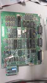
In the same loot acquisition mission in which I obtained that ADM-3A+ and H-19, I also obtained this Kaypro 2-84 (and an Osborne 1, but I haven't cracked it open yet).

There were no screws in the case and some stuff was obviously damaged, so I figured I ought to tear it to pieces and figure out what I needed to have ordered while I finish the H-11.

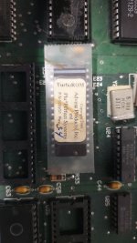
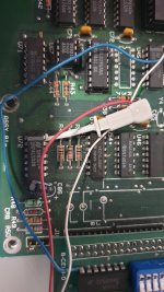
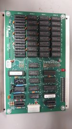
It appears to have the Advent TurboROM installed, and was upgraded to double-sided drives.

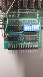
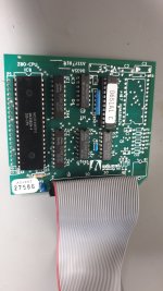
It also appears to have a 1mb Advent RAM disk installed, with 768k populated.

I haven't dug around the web very hard for manuals yet, but apparently the TurboROM also adds support for 720k floppy drive and hard drives. I shall have to suss out what kind of hard drive interface is required for this, and if anyone cobbled together some kind of SD/flash/USB drive contraption for these things. Apparently the RAM drive interface is through a few IO ports rather than banking, so I don't think I can use it for a huge pile of banked RAM for Fuzix or something, unfortunately.

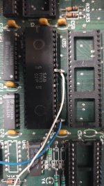
I tested the power supply and tested the video board enough to verify that I had high tension and a raster, but there are pins bent and broken on the Advent carrier that slots into the CPU socket so I haven't gone any farther than that. I'm not going to do anything else with it until I finish the H-11. I've gotta stop chasing so many shiny things at the same time and never finishing anything!

Anyway, I think it will be a neat machine. Some photos of the unusual stuff are attached, for those of you who are interested.
 

Attachments

  • 20220823_194734.jpg
    20220823_194734.jpg
    455.6 KB · Views: 26
  • 20220823_194744.jpg
    20220823_194744.jpg
    753.4 KB · Views: 27
  • 20220823_194754.jpg
    20220823_194754.jpg
    513.7 KB · Views: 27
  • 20220823_194810.jpg
    20220823_194810.jpg
    459.2 KB · Views: 27
  • 20220823_194818.jpg
    20220823_194818.jpg
    606 KB · Views: 26
  • 20220823_194857.jpg
    20220823_194857.jpg
    503.8 KB · Views: 26
  • 20220823_194913.jpg
    20220823_194913.jpg
    632.3 KB · Views: 27
Last edited:
Very nice - glad to see that Kaypro getting some attention. I never knew about the 1MB installed - so that's what that add-on board was. It's good that you were able to get that much further than I did, especially so quickly.
I've gotta stop chasing so many shiny things at the same time and never finishing anything!
My wife laughed at this line; she thinks that I should do the same.
 
Very nice - glad to see that Kaypro getting some attention. I never knew about the 1MB installed - so that's what that add-on board was. It's good that you were able to get that much further than I did, especially so quickly.

My wife laughed at this line; she thinks that I should do the same.
Your wife would do a "ROFLcopter" if she saw the inside of my garage.
 
So I've been reading the schematics instead of working on the H-11. ...... .....

Shame on me.

But since I did, interesting things to note:

The 2-84 appears to be exactly the same board as the 4-84, just without the 300 baud modem and RTC. The RJ-11 connector is there, but none of the rest of it is populated.

The primary serial port appears to have jumpers to drive the SIO with an external clock on pins 15 & 17 of the serial connector. I suspect this means it could be driven past 19.2k! :O If the CPU could keep up haha.

The SIO port for the internal modem isn't hooked to anything. This might be an interesting place to wire up a wifimodem, although I suspect that the antenna would have to be routed to the outside of the metal case. That SIO channel is hard-wired to 300 baud, but the pin could be lifted and probably driven at whatever baud rate you wanted using a PWM output pin on the ESP8266 or ESP32 module of the wifimodem itself.

Some of the flow control pins on the serial "printer" port aren't hooked up, but they do come out to test points. I think they could be routed to the port with fly wires (through a MAX3232 on a piece of perfboard or something), turning the serial "printer" port into a "real" serial port too.

The PIO and RTC and a handful of discrete components could be populated to give it a RTC. Powered by something less prone to leakage than the nicad that was in the 4, of course! D:
 
One thing that I thought was a cool idea was to connect up one of the serial ports to a Raspberry Pi 0W, and then, using a terminal program, work like you were connected to the internet through one of those old dial-up accounts. That is something that I would like to do with one of my Model Ts.
 
I routinely used the SIOs on my 2X (2/84) at 38.4K, but in synchronous modes for specialized purposes (crude digital oscilloscope, IR remote controller, etc). The 4MHz Z80 can keep up... but you typically have to use special (polling) routines (and NOT interrupts).

Unfortunately, the built-in modem is 300 baud, which was practically obsolete on day-one. I populated the RTC on mine so I could run CP/M 3 (with RAM hacked to use 256K chips). I never bothered with the hard drive interface because it was not SASI. In fact, that interface is actually a general-purpose I/O expansion port and for the HDD there is an adapter board (I/O port selection logic) between it and the WD1002 HDD controller.

Kaypro was striving for a "Universal Mainboard" so essentially all units sold as of 2/84 used the same mainboard. They even did a special version of the universal mainboard that could be fit into the older Kaypro 10 cases.
 
Unfortunately, the built-in modem is 300 baud, which was practically obsolete on day-one. I populated the RTC on mine so I could run CP/M 3 (with RAM hacked to use 256K chips).

Seems a real shame to be wasting that whole half of that modem/printer SIO!! It's tied to the same baud rate generator as the keyboard side of the other sio, it looks to me like. So I figure, a pin could be lifted on the SIO and the baud clock could be supplied from somewhere else.

Question is, where. I guess it could be tied to the programmable baud rate generator, but then you've got two ports that always have to run at the same speed, and that would be annoying.

But if I were going to do something with that side of the SIO, it would be some kind of ESP-based wifi modem. I figure TTL level rx, tx, rts, and cts can be pulled off the unpopulated sockets for the modem IC. The ESP-32 has a programmable PWM generator that is meant for LED dimming or DC motor control, but you can program it to produce a nice 50% duty cycle square wave anywhere between 0 and 40 mhz iirc. I don't think the ESP-8266 has a pwm generator though, but I can't remember. It's not hardly beefy enough to handle ssh anyway. So the wifi controller could clock the modem sio with its pwm and you could drive it as fast as the cpu could handle.

It seems like it would be appropriate, to repurpose the fsk modem stuff for a wifi one. :D

Tell me more about your 256k ram mod, please. How does it connect to the board, and how do you have your banking scheme set up? Fuzix requires a timer interrupt for context switching as well, and is easiest to get working with a 4x16k flex banking scheme. From what I've read, that is!
 
I describe my 256K mod here: http://sims.durgadas.com/kaypro/kaypro84x.html. There is a schematic referenced there, which is oriented towards a piggy-back on the Z80. The software interface to the bank switching is described there, it was simple and wasted some of the memory, but worked. It provides a flexible common memory boundary scheme, so you can make common memory almost any size you want (4K increments).

I made the modifications directly to the mainboard, using spare sockets and running wires on the bottom of the board (cutting a trace or two, also). After a year or so, the mainboard started getting flaky and I had to replace it. I never modified the replacement, so my 2X is back to 64K. When I wrote the simulator, I made options for this mod and was able to run my old CP/M 3 port in that environment.

As far as expanding the Kaypro, given modern ease of designing and fabricating PCBs it might be easier to use the expansion port (HDD connector) and add another UART - or even a parallel interace - to your ESP-32 or equivalent. I presume that "RAM disk" expansion does the same thing.
 
Looking at your photos closer, I see that this RAM disk device is really not Kaypro-specific, and uses a Z80-piggy-back card to implement access to the RAM disk.
 
FYI, I added the RTC chip to my 2X, and that chip is capable of generating a periodic interrupt. I used the 1-sec interrupt (for the CP/M 3 TOD clock), but it does provide a 100mS option (that's the fastest it can interrupt, though). I'm not sure if the MM58167 is still available, though. If you add the PIO anyway, you could probably use an input there to generate a faster interrupt.
 
Hoo! I fixed it enough to get the ROM prompt! Now to get a gotek working on it and try to boot the thing.....

I'm going to have to find an RJ-22 cable for the keyboard, too. Not nearly as common as they used to be!!
 
Back
Top