• Please review our updated Terms and Rules here

KIM-1: source for edge connector?

AdamAnt316

Experienced Member
Joined
May 23, 2016
Messages
230
Location
Massachusetts
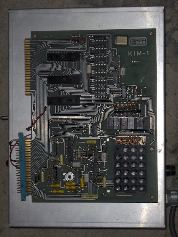
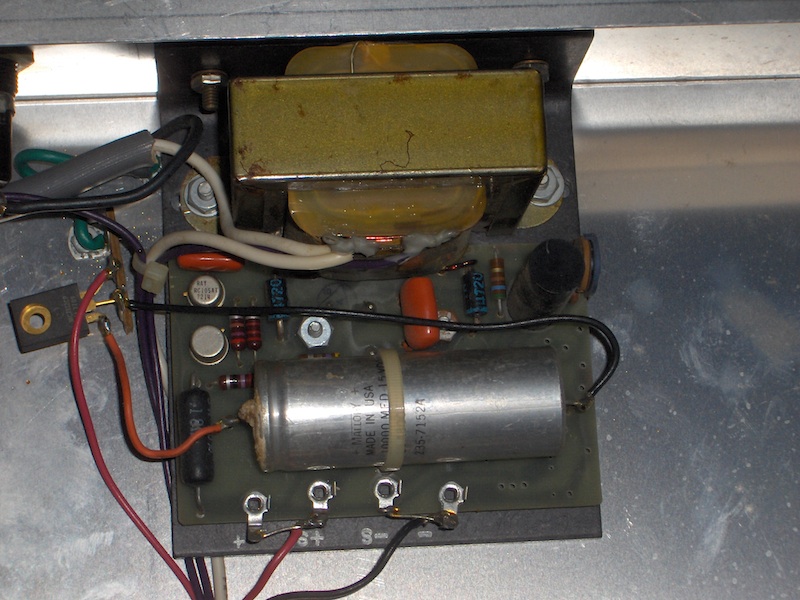
Hello everyone. I've had a KIM-1 for some time now, though I have yet to try it out. It came attached to a chassis with a power supply underneath, but the connector going from it to the board has seen far better days (at least a couple of the pins are broken off, including some of the power ones). One of the online FAQs identifies the connector as a Vector type R644 (once offered by Radio Shack as part# 276-548 ), which is offered by Mouser and other sources, but for prices I find absurd (both DigiKey and Mouser wants $20.66 for one, though DigiKey also offers a R644-3F wire-wrap version for 'only' $13.38 ). Is there another option? A local electronics store has some edge connectors, though they're more like the type seen used for floppy disk drives, with a much more narrow pitch. Any ideas? Thanks in advance.
-Adam
 
An EDAC 305-044-500-202 might be a suitable replacement. $10 each at Mouser.

44 contacts, 0.156" contact spacing, wire hole solder eyelet termination
 
Thanks for the tips thus far. I will keep these options in mind, particularly the EDAC one. Dwight, what search criteria did you use to find them on eBay? Not sure I'd want to resort to overseas sellers, but it's nice to know one's options.
-Adam
 
Again, thanks, Dwight. Searching for "edge connector 44" yielded numerous results, though about half of them were for some oddball car connector that doesn't even have 44 pins. Found a local seller who had the Cinch version for $4.75 apiece, so I bought two of 'em. There were cheaper options, but I'm hoping that the seller being located in MA means they'll show up sooner.
-Adam
 
I once had to scrap a VIC-20 and its cartridge connector turned out to fit perfectly. I then soldered it on a Eurocard (16 * 10 cm.) and equiped it with several 64-pins A/C DIN connectors. This meant I could expand the KIM with more than one card.

- Ruud
 
My new edge connectors arrived yesterday. Thanks for all the suggestions! Now, of course, the questions turn to exactly how to wire the new one up. The wires going to the two top-most pins (1 and A) of my existing connector have broken off, one in the past, and one when i was trying to repair the damage to the broken one. One of them is red, leading from the + and S+ terminals of the power supply under the chassis the KIM-1 is mounted to. The other is black, leading from the - and S- terminals of said power supply, and is bridged to pin K of the connector. Another red wire, connected to pin N, is from a 12-volt regulator which feeds off of the main filter capacitor of the power supply. From the diagram on page 8 of the user manual, I assume the loose red wire goes to pin A, and the loose black wire goes to pin 1. Is this correct, or am I misreading the diagram? Here are some pictures of what I'm dealing with:
moskim1.jpg

(appears that the black wire was still connected to pin 1 at the time)

moskim1_ps.jpg

(I will replace the electrolytic capacitors before powering it up, of course)

Again, thanks in advance!
-Adam
 
There are several on line copies of the user manual. I suggest
you check them out. The answer ti your question is on page 8.
A is +5V or VCC
N is +12V or VBB
1 is Ground common or VSS
K should be tied to ground if you want to boot to on-board ROMs and other on-board resources.
I recommend putting shrink tubing over the terminals A and 1 as they are
easily shorted.

I should mention, the +12v is only needed for the cassette interface. The KIM will otherwise
run without it connected.

Dwight
 
Last edited:
Thanks for clearing that up, Dwight. It's about what I figured; I did indeed find a user manual, as I linked to above, but found the diagram and description confusing. This is the part which had me wondering: "The jumper from pin A-K to Vss (Pin A-1) is essential for system operation. If you expand your system later, this jumper will be removed and we'll tell you what to do to pin A-K." A bit confusing to name it 'A-K' when there are pins on the connector labeled A and K, and also the edge connectors themselves are labeled A and E.

Also thanks for the note on shrink tubing; whoever wired the original connector did use it, since the shorting risk is doubled on the wire wrap/chassis pin style of connector (Viking 7309) they used. I chose to buy the style of connector with solder lugs for this very reason, but may add new shrink tubing anyway. As for the cassette thing, I don't know who made the power supply in my second picture, but it has provisions for the 12V power (either factory or added-on by the user, I'm not sure which), so I'll run that line to A-N.
-Adam
 
The KIM board decodes 8 each 1K byte blocks of memory. It does this by only
decoding through address A10. This leaves out decoding of the remaining addresses
of A11 through A15 that the 6502 is capable of.
What this means is that the 8K of memory will repeat over and over 32 times if using
address beyond 8K.
The KIM has a way to restore the full address space and that is the signal called DECEN.
When left High it disables the partial memory decoding of the KIM board.
In order to use more memory requires more complete decoding.
One would do this one of two ways.
One way would be to completely eliminate the KIM's memory window and provide
external ROM, RAM and I/O.
Another way would be to decode the rest of the missing memory addresses and
only allow the KIM's memory and I/O to be seen by the processor when addressing the
lower 8K.
This would be done by using a decoder to enable the DECEN signal when it is addressed.
The one issue with doing this is that the reset and interrupt vectors exist in the high memory.
Normally for the KIM, the KIMs ROMs mirror in that address space.
With the KIM limited to only the first 8K, one has to provide either a method to allow the KIMs
memory in high memory on boot and switch it out later or supply an independent ROM
with the vectors at the high memory.
One might ask, why not have the board work the other way around. That is with no wire
connected, the KIM would boot but without the line grounded, other memory mapping being used.
The answer to that is "cheap". The 74145 decoder chip was selected. The way it works is that
the outputs 0 to 7 are deselected with the input D high.
Consider that the chip is actually a 4 to 10 decoder or BCD.
Had they chosen a 74138 instead, I'm sure history would be different.
Dwight
 
Interesting stuff, Dwight, thanks again. I know you've mentioned DECEN in the other troubleshooting threads, and I had it in mind when I was puzzled about how the 'new' edge connector was to be wired, which is why I asked for clarification as to whether everything was wired correctly. A lot of this stuff flies over my head, but there's definitely a method to its madness.

And yes, "cheap" is right. Granted, I don't know how one type of 74xxx-series IC was priced against another in the '70s, but I know that a fully-assembled KIM-1 sold for $245, at a time when an Altair 8800 or similar in kit form would set you back twice that or more. Of course, the KIM-1 was intended more for engineers than hobbyists, hence the lack of a power supply or a straightforward way to apply power to one. When I first saw a KIM-1 in high school, I couldn't fathom why they designed it that way, but it (kinda) makes sense now.
-Adam
 
Back
Top