• Please review our updated Terms and Rules here

KIM-1 tty

DadDudeTheBarbarian

New Member
Joined
Jan 29, 2024
Messages
3
Hi folks -- I'm trying to get my KIM-1 tty connected to RS-232 through a (rather spendy!) 20mA loop to RS-232 converter, and so far I've had no success. While I bang my head on this, I wanted to see if anyone that has used this or a similar converter would share how you had it hooked up to the KIM?

Thanks.
 
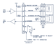
I have a BB-232CL4R, but the same connections should work. On the application (lower) connector,

pin R to T+ (keyboard return)
pin T to T- (keyboard)
pin S to R+ (printer return)
pin U to R- (printer)

Note that this is a little contrary to common sense but that's what worked for me. You don't need power on the converter though it shouldn't hurt.
 
As this is your first post, welcome to VCFED.

You need one side of the current loop to supply the actual voltage supply (the active end). If you have two passive ends, it won't work. Worth checking...

Also, aren't there some links (also on the edge connector) to make to enable the TTY interface? I am sure this is documented fully in the manual.

Dave
 
Yes, bridge 21 to V.
Thanks, that's how I have my setup wired. I'm seeing a couple of things that look odd to me in this configuration. I'm measuring 0.2v across pins R and T when keys are pressed on the terminal, and a steady 0.7v across pins S and U; I expected to see something closer to 5v based on my (possibly flawed) reading of the diagram in the KIM-1 manual/what daver2 posted. I do see data coming out of the loop converter on the keyboard terminals on my scope, and while I see a similar pattern coming off of S and U, I don't see anything that looks like a signal change on those pins in response to seeing the RUBOUT character. I guess I'm going to chase the KBD line back through to U2 and see what I see.

I've also read in the Corsham IO Board documentation that when you connect pins V and 21, pressing the RS button will *not* enable the 7-segment displays; mine turn on but are clearly missing segments. When pins V and 21 are open, the displays are fine and the KIM works as expected. Can anyone confirm expected behavior when V and 21 are connected?

Thanks folks, appreciate the help.
 
I'm seeing a couple of things that look odd to me in this configuration. I'm measuring 0.2v across pins R and T when keys are pressed on the terminal, and a steady 0.7v across pins S and U; I expected to see something closer to 5v based on my (possibly flawed) reading of the diagram in the KIM-1 manual/what daver2 posted.
It's a current loop; the voltage level on it is ignored, and I reckon will vary depending on where you're measuring it, the length of the cable and various other factors.
 
When V and 21 are connected, you should see nothing on the LEDs, maybe a brief flash when you press RS. The LEDs function and programs can use them, but the monitor won't light them if those lines are wired together.

Also, what @cjs said about current, not voltage.
 
When V and 21 are connected, you should see nothing on the LEDs, maybe a brief flash when you press RS. The LEDs function and programs can use them, but the monitor won't light them if those lines are wired together.

Also, what @cjs said about current, not voltage.

Thanks for the confirmation. I'm going to chase down the LEDs first.
 
Back
Top