• Please review our updated Terms and Rules here

Led Par psu problem

Jazzburger

Member
Joined
Mar 19, 2024
Messages
26
This is not specifically a computer problem, but I have found great help from this forum, when I have worked on pc power supplys, so here we go.

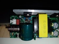
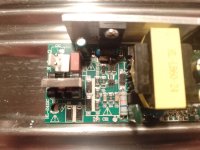
I have this damaged led par spotlight. The tube fuse is dead and the psu-board has all kinds of visible damage. I would like to try to repair this.

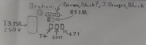
So I would need help to identify these components, especially the resistor. The red one is fuse, and the small ones are diodes?

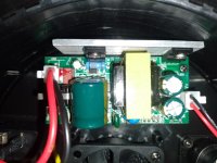
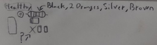
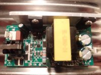
I have (tried) written down the markings on the visibly damaged components. I also have "identical" working spotlight for comparison. But the psu board on that is different? (Yes, these are very cheap asian spotlights so there is no consistency.)
 

Attachments

  • Broken board.jpg
    Broken board.jpg
    1.2 MB · Views: 14
  • Broken.jpg
    Broken.jpg
    273.2 KB · Views: 15
  • Healthy board.jpg
    Healthy board.jpg
    1.7 MB · Views: 15
  • Healthy.jpg
    Healthy.jpg
    246.5 KB · Views: 13
The 'healthy' resistor is 0.33 Ohms +/- 1% tolerance.

If the 'faulty' resistor had a black band in place of the silver band, this would be 33 Ohms +/- 1% tolerance.

I would expect both of them to be the same though!

You may find that the 'faulty' resistor is only scorched as a result of damage to D4. You may be able to remove it and measure the value. It will clearly need replacing anyhow.

D4 is clearly toast. I assume the RS1M came from the healthy board?

You really need to identify the circuit IDs for the other components. These will give you an idea what they are to start with.

471 is a good indication of a 470 Ohm resistor (assuming an Rn circuit ID).

200 could be a 20 Ohm resistor (but this would not be a standard part)?

T4 - no idea.

You probably need to remove the large capacitor from above the fried components to observe the circuit IDs for these components.

However, these components may have died as a result of a fault elsewhere drawing a high current.

Dave
 
Thank you!

Yes, I would guarantee the resistors are the same.

I think i got the RS1M from the faulty board somehow. The marking is same on the healthy one.

Also the 471 and 200 are same on the healthy board (maybe not same polarity), but the T4 is completely missing from the healthy board? I have no idea why is that.

I will desolder the big capacitor after a worktrip and I´ll get back to this.

Thank you very much Dave!

-TK
 
There's a good chance D4, Q1, and Q2 are all shorted. There could be a shorted/leaky capacitor that overloaded the supply. You'll have to follow the power path down to see what is all blown up. Chances are the blown up resistor is just a side effect of the root cause.
 
Large capacitor removed. No visible damage under it. Sorry for the bad quality.
 

Attachments

  • IMG_20250211_191638_065.jpg
    IMG_20250211_191638_065.jpg
    1.2 MB · Views: 5
I am trying to see the silk screen markings, so I need a decent photograph I am afraid.

It does look like a diode on the left and two resistors in the middle and on the right.

Dave
 
There is a SMD diode identified as a T4 part.

So, all we have to do is identify the resistors. I think we did that from the markings on the 'good' board.

We just have to make sure we know which way around the diodes should go. Is there a plus (+) sign on one of the pins - or some other polarisation indication?

The diodes themselves should have 'bar' to indicate existing polarity.

Dave
 
Here is better picture. I think the diodes has some stripes on the other end.

Thanks!
 

Attachments

  • IMG_20250211_201636_978.jpg
    IMG_20250211_201636_978.jpg
    1.4 MB · Views: 5
Assuming you can find all of the right components, you're going to have a problem with the PCB being burned.

You need to remove ALL of the charred PCB material and sputtered junk on the PCB, because it's conductive. With it being on the high voltage side, leaving any of it behind can allow flash over and cause it to blow up again.

Definitely replace all of the capacitors, they look like junk Teapo-Cheapo or some other no name crap. The mains side cap on the "good" power supply looks like its also failing, the top is slightly domed, it should be perfectly flat.
 
Thats agood point. The soldering is going to be hard job anyway because these components are so tiny. I will replace the caps also, its the easiest job here. Thanks.
 
Now all the components are replaced. When I tested the spotlight, the tube fuse blew up. I was using the same type of fuse that the working spotlight is using. What is going on here? According to seller, these par spots are 150w and 250v.
 
What do you mean by 'tube fuse'? Is this the fuse within the spotlight?

If so, the 'original' fault (causing the original components to burn) is probably still present. You may have replaced the components that died as a result of another fault - but not the faulty component itself. Which I did point out in post #2.

The reason the fuse may have gone this time (as opposed to the components) may be down to luck or chance rather than anything else.

Dave
 
If the mains fuse blew up, the fault is probably somewhere on the primary side of the power supply. You likely have a short on something, you'll need to start hunting for shorted components.
 
It`s the glass tube fuse next to the power input. The apartments mains fuse breaker also flipped. I`ll hunt for the failed components more.
 
Depends on what blows up. Passive components are cheap. It starts getting expensive when you blow up mosfets, regulators or control ICs.
 
Back
Top