• Please review our updated Terms and Rules here

Leningrad 48K issue...

channelmaniac

Veteran Member
Joined
Oct 10, 2008
Messages
813
Location
Dallas, TX Metromess
Hey folks!

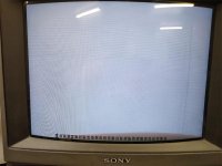
Received a Leningrad 48K PCB from a friend and built it... got the ROMs programmed... and BOOM, sync issues. Turn out I was missing a jumper wire. Installed that and I have a screen with all the text on a single line at the bottom.

Have y'all ever seen this issue? The only thing I can think of is the wonky /IRQ signal I'm getting, but I don't see anything else.
 

Attachments

  • SpecyScreen.jpg
    SpecyScreen.jpg
    64.2 KB · Views: 23
GOT IT.

Two issues. First, the ROM code I was given was bad. Downloaded another set for it from the web, but it was 16K. Broke it into 2 and programmed 2 other EPROMs. BOOM! "(C) 1989 Sinclair Research Ltd"

Keyboard was something else. The system was going off into LaLaLand and I was sure the missing /IRQ was the culprit. Went round and round with that stinkin' circuit trying different chip types and I think the 74H blew the crystal. Soldered in a new crystal and was looking at the scope wondering why it was so low on the input that it wouldn't trigger the LS04.

The 1N914 at D1 was backwards.

Sigh.

Installed it the right way and now I have /IRQ and now the /IORD signal is reaching the LS257s. I don't have a keyboard, but I have a jumper wire and touching the contacts produces keystrokes visible on the screen.

I'd call that a success. Now to order a keyboard PCB. :)
 
Remake of a Soviet-era clone. :)

It uses English ROMs and in pure Soviet style - no places marked for filter or bypass caps and no connectors for power, video, or tape... just wires to back of case connectors.

I looked at pics online and used my multimeter to find vias that I could use for installing several bypass and a single filter cap. I used the breadboard area to install a 5vDC barrel jack and a filter cap and used wires to bridge that over to the power/ground traces. I also used .1" header pins for connections for tape, video, and reset connections. There's no ground pin for video so I found a via close to the video output pins and soldered in another .1" header pin.

Fun, no? :)

I also helped my friend troubleshoot his after he built it. He had a few more issues than I did.

  • Bad Z80 CPU
  • Bad ROMs & ROM sockets (soldered legs on the old ones damaged the sockets)
  • Solder problem on CPU socket causing a problem with an address line signal reaching the ROMs.
  • .1uf bypass cap was installed on the /CAS line holding it down. Removed it.
  • .1uf bypass cap was installed on the RAS line holding it down. Removed it.
  • Replaced several bad Russian logic ICs.
  • Fixed bent pin 1 on a 74LS257

If you wondered about the RAS signal listed, yes, it has RAS and /RAS. The RAS is used by 4 of the LS257 chips on pin 1 to toggle the inputs where /RAS is used to strobe the row addresses into the RAM.
 
Back
Top