• Please review our updated Terms and Rules here

Looking for the PDP-8/I Control Panel Assembly Bezel Casting drawing

smp

Veteran Member
Joined
Oct 4, 2011
Messages
1,722
Location
Bedford, NH, USA
I am looking for the PDP-8/I front panel bezel casting drawing, for a possible project to recreate the bezel in 3-D printing.

I looked on BitSavers in the /PDF/DEC/PDP8/ section and I see that the PDP-8/I Assembly Parts List is drawing A-PL-8I-0-0. There I see that the Control Panel Assembly drawing is E-AD-7005554-0-0. And, I see that the Control Panel Assembly contains the Bezel Casting Rework drawing E-IA-7406188-0-0.

I believe I would be looking for the Bezel Casting Rework drawing E-IA-7406188-0-0 in order to obtain all the dimensions necessary to describe the bezel for 3-D printing. However, so far, I have not been able to find a copy of the Bezel Casting Rework drawing.

Can anyone offer up a pointer to where I might be able to obtain a copy of the bezel drawing? Also, has anyone else ever investigated creating a copy of the DEC PDP-8/I front panel bezel? If so, I would appreciate any info or pointers on that project, so I don't go off and re-invent something that has already been accomplished.

Thanks for listening. Thanks in advance for any advice or pointers that you may have to offer.

smp
 
If you don't find the original drawings then you're set to recreate it from measurements of an original panel. I'm doing the same as you but for an -11 console.
I haven't seen an 8i panel but if it's anything like the other DEC consoles I've seen, it's likely the same relatively simple pattern that doesn't use compound curves.
The tools I use are a digital caliper (the larger the better), angle gauge, radius gauge, height gauge and surface plate.
If you don't have the original in front of you, you can still get good results but it's more time consuming. Getting someone else to measure their panel is ok but they may not have the same tools. There are ways you can help them, for example sending them a pdf of radius corners to print and cut out. Or, put a round coin flat against surfaces and details being photographed. Then you can always scale from the coin diameter even when it appears as an ellipse.
 
Thanks very much for your reply - at least it keeps my request on the top page of posts for a little while longer!

Believe me, if I had an original example, I probably would not be looking to create a 3-D printed replica! I have nothing, and I am looking for the bezel drawing, so I can investigate what it may cost to reproduce one. With no original (in any sort of shape) and no drawing, I am reduced to making guesses, and I'd rather not be guessing.

If no pointers to the drawing are available, does anyone have a PDP-8/I bezel - whole or in pieces - that could be measured?

smp
 
If no pointers to the drawing are available, does anyone have a PDP-8/I bezel - whole or in pieces - that could be measured?

I do have one that I could try to find some time to measure (or maybe even model) for you.

Vince
 
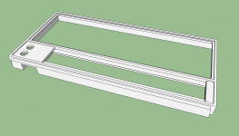
I started a drawing...

8iBezel.png

As is often the case, it looks way better than it is. It's still missing the slot for the panel artwork and all the other attachment stuff on the backside and edges. (You have mount the lights PCB, the switches PCB, and then there are also threaded holes to mount the whole assembly, which hinges out for service.)

You'll probably want something for the light guide thingy too.

Vince
 
Thanks very much for your effort, Vince.

Of course, the goal is to end up with a drawing that I can provide to a 3-D printing business, and get an estimate of the cost to produce one (or more) of these bezels. That drawing would have to include all the bits that you indicate you don't have yet. If you are up for it, I would love to see what your model looks like when complete.

smp
 
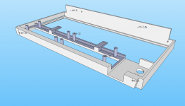
Bezelb.png

OK, I had a go at more of the drawing. The slot for the artwork is there, as are mounting points for the light mask and for the switches PCB. (The lights PCB actually mounts to the light mask.) I put lower mounting tabs for the light mask, but not the slotted angle brackets that mount to the #6-32 holes at the top. I couldn't think of a good way to make that simpler to fabricate and still have the depth be adjustable.

It's drawn in Sketchup, so the holes aren't drawn threaded (that's really hard in Sketchup). You'd have to drill and tap, though I did stick undersized holes to help center things and a few text labels on the drawing to make it clearer what to do. Mostly everything is #6-32, I think, except the bottom right hole (left as you look at the back) is #10-32.

The tabs for the light mask are just drilled, but there are #10 screws that go into threads in the light mask there. I also modified the tabs so they're part of the bezel, rather than the original assembly of a screw, spacer, and bar stock.

It's drawn from my (sometimes crude) measurements, so it may need some tweaking to line up perfectly with vintage parts. (Just think of it as untested.)

Vince
 
That is a great drawing Vince!
Don't worry about the threads, the "in thing" (literally) for 3D prints these days are nutserts, which are heated and pressed in, or you can press-fit and superglue instead. Hackaday recently had an in-depth article on them.
10-32 and 6-32 are readily available: https://www.ebay.com.au/itm/150PCs-SAE-Rivet-Nut-Kit-Rivnut-Nutsert-Assort-Set-1-4-20-10-32-10-24-8-32-6-32/363055279052
Also [url]https://www.ebay.com.au/itm/AWS2-1032-Nutsert-Insert-10-32-Material-Thickness-062-Up-RND-Nutsert-Dia/254713607804

[/URL]
 
Thanks very much for your effort, Vince.
You are welcome. (It's something I've thought of doing from time to time but never made time to actually do.)
Of course, the goal is to end up with a drawing that I can provide to a 3-D printing business, and get an estimate of the cost to produce one (or more) of these bezels. That drawing would have to include all the bits that you indicate you don't have yet. If you are up for it, I would love to see what your model looks like when complete.

There are quite a few challenges to 3D printing something like this. It's a lot of area and a lot of plastic, which is probably why Shapeways wants over $300 to print one. A less expensive printer would need the thing broken down into printable pieces that could be assembled later. A fair amount of support material might need to be printed (and then removed). It's big, so printing will take a good long while. (And so on.)

I'll probably putter with it a little more and eventually put it up on my 3D page, but at least I think we've got most of the dimensions recorded now (modulo any measurement errors I've made).

If you are masochistic, the files are online here:
http://svn.so-much-stuff.com/svn/trunk/3D/8IPanel/
The Sketchup drawing is in inches; if you want mm, be sure to get the right STL file.

Vince
 
Thank you very much for all this effort, Vince!

Whew! $300 is a bit more than what I was hoping the cost might be. Did you actually submit files to Shapeways for an estimate?

I am not familiar with any of the CAD tools, so would you please indicate specifically what subset of your files would need to be submitted to a 3-D print house for an estimate?

Most of all, please post back here with any updates that you make, so I can stay up-to-date with the latest files.

Thanks very much, once again!

smp
 
Thank you very much for all this effort, Vince!

Whew! $300 is a bit more than what I was hoping the cost might be. Did you actually submit files to Shapeways for an estimate?
Yes, I uploaded the exported Bezel-mm.stl (which is in the usual 3D printer format), and the estimate came in just over $300. I had expected at least half of that, just because the thing is so dang large.
I am not familiar with any of the CAD tools, so would you please indicate specifically what subset of your files would need to be submitted to a 3-D print house for an estimate?
The .skp file is the Sketchup drawing. Real CAD guys will scoff at Sketchup, but it was free and what I learned with. It lacks a lot of "cool" features (like threads), is easy to mangle the drawing, etc. Oh well.

Anyway, there's a plug-n to export .stl files. If you export in inches, which no-one else would do unless they had a need to re-draw the thing with another tool, you'd get the Bezel.stl file. If you export in mm, you'd get Bezel-mm.stl. That's the standard format for most 3D printing, and what I uploaded to Shapeways to get the ball-park estimate.

What's needed now is someone with a 3D printer, and a whole lot of gumption, to turn it into something printable with reasonable cost and effort.
Most of all, please post back here with any updates that you make, so I can stay up-to-date with the latest files.

Thanks very much, once again!

The SVN repository URL I posted before should track the changes as I commit them. If you've got Subversion installed, you can also use that URL to check out all the files.

You are welcome!

Vince
 
It also occurs to me that it should be possible to, say, create a wooden mock-up and then mold and cast to get a reasonable way to make more bezels inexpensively. That seems like it might be within a reasonable budget of time, money and expertise. Quite possibly easier, and certainly cheaper, than contracting the 3D printing.

Another advantage is tuning the mock-up to actually fit the PCBs and required mounting, if there turn out to be issues there.

Vince
 
My big printer is large for a hobby printer and it will only do 13.7 inch (350 mm) objects. On a narrow diagonal about 19 inches so this is quite a bit too large to do as a single piece. I would have to spend somewhere between 500 and a thousand dollars to upgrade to allow me to print this as a single piece. I think Shapeways price isn't really that excessive. I dummied up a larger version of my printer in the slicer program and it tells me this would take about 18 hours as a fast print setting. This would not look the best but would be the way I would verify fitment of everything. Print a good one later at twice the time. The estimate was for a little over 300 gms of plastic or around $8. So not much for the material, a lot for the machine and time.

How are your wood working skills? This would be reasonable to do in wood and you could paint it in a white/cream crinkle finish and it could look good.
 
Metal was traditionally cast by one of two methods: sand casting and die casting. Die casting involves much the same types of equipment as injection molding of plastics and is probably out of reach for most DIYers. Most of the cast metal bezels I've seen on electronic equipment were die cast aluminum. The technique lends itself to finer tolerances and smoother finished surfaces, but again, is probably out of reach for most hobbyists. Sand casting is another animal entirely. There are videos online showing how to equip and operate a home foundry and create aluminum sand cast parts that are rather complex. Somewhere in between die casting and sand casting is a technique that has migrated from the jewelry industry into much wider use. That would be investment casting, often known as "lost wax" casting. A variant of that technique, known as "lost PLA" might be the way to go if you're going to try to cast a replica PDP8 bezel.

https://all3dp.com/2/lost-pla-casting-guide/
 
Metal was traditionally cast by one of two methods: sand casting and die casting.

I was just thinking of two-part silicone and 2-part resin for the mold and casting respectively. That's generally doable at home, and you'd probably not even need to pull a vaccum for this (assuming you design the mold not to trap bubbles).

Vince
 
I've been chatting offline a bit with smp about making a bezel assembly out of wood, and today I started to extract 2D drawings from the 3D, simplifying just a bit, and producing a set of "layer" drawings. I think that makes it a little easier to visualize, and also allows a sort of glue-up construction of a model made of wood or similar. I screwed up the bottom (switches) area slightly on the first couple layers, and it's getting late, but maybe tomorrow sometime I'll have something to show.

I'm thinking of a layer where the switches PCB attaches, a layer where the lights PCB attaches, a layer where artwork is positioned, a layer of black trim (also mounts the keyswitches), and a layer of white(ish) trim, all glued together from bottom to top with the appropriate edges aligned.

The simplifications would make it difficult to use the thing on an actual 8/I, but should make it easy to envision and assemble (while still looking quite similar to the real thing).

Vince
 
That sounds intriguing, Vince!
I'm wanting to see how this can be realized. It could be a huge help to those of us who want to build up a replica front panel, but have nothing to start with for holding it all together.
Looking forward to what you come up with!

smp
 
OK, here's my attempt:
View attachment 8iBezel.zip

The layers from the bottom up are:
swblock.pdf
lightsblock.pdf
artblock.pdf
blacktrim.pdf
whitetrim.pdf

No one has built anything yet from these drawings, so consider them appropriately experimental!

Let me know if these look comprehensible, useable, inaccurate, or whatever :).

Simplifications:
The taper of the top surface has been removed.
The black trim has multiple heights in the original; this one has two of those heights conflated for easier construction.

It is possibly easier/better to construct the thing with 3/16" shaved off the perimeter, then use 3/16" sheet goods painted with textured off-white to form a box in which to hide the PCBs, RasPi, etc.

Likewise, it might be better to elide 3/8" from the bottom, and attach a 3/8" sheet down there instead, which would keep the thing from falling over when you try to play with the switches.

Speaking of which, we need a decent switch solution. I'm thinking the switch bodies Oscar is providing might be OK, if they can be equipped with full size rockers and spaced the appropriate distance apart.

Vince
 
Continuing to daydream about this, I've been looking at solutions for the "switches" board. Going with vintage footprints and dimensions is hard -- those honking big slide switches just aren't popular (available) anymore, and I hate to think of people dis-assembling vintage gear to scavenge them. That argues for a solution made of (more) modern parts.

From what I've been able to determine, the most likely replacements look like the 7000 series from C&K, the E-switch 300 series, and the MTS-100 series switches that come with the PiDP-8. These are all roughly equivalent in physical size and shape, at least for the switch body itself. There's considerable variation in the "cosmetic" bit -- the plastic paddles or rockers (or metal bats -- yech) and their supports. There are also options for the physical mounting, which make some of them easier to align, etc.

One issue created by a new switches board design, though, is that it won't likely have the same height as the original, which affects the drawings. They'll need to be modified to support the new switch assembly in the correct position relative to the front of the bezel assembly.

Vince
 
Back
Top