AK6DN
Veteran Member
Given that voltage drop under load, I would suspect oxidized connectors that have a higher than normal resistance, giving a substantial voltage drop under load.
Are BDCOK and BPOK used as "remote sensing" that feedbacks local remote voltage back to power source ? If the returned voltage is too low then the power source will pump more voltage. Is it correct ?There is very little current flowing in the control signals - so there will be very little voltage drop across the cables. However, 4.6V is still too low!
The main 5V rails will have an appreciable current flow - and hence voltage drop.
Dave
It is part of my investigation as well. Thanks for the comments.Given that voltage drop under load, I would suspect oxidized connectors that have a higher than normal resistance, giving a substantial voltage drop under load.
No, they are just logic levels. H is power DC or AC OK, L is power not ok.Are BDCOK and BPOK used as "remote sensing" that feedbacks local remote voltage back to power source ? If the returned voltage is too low then the power source will pump more voltage. Is it correct ?
Are BDCOK and BPOK used as "remote sensing" that feedbacks local remote voltage back to power source ? If the returned voltage is too low then the power source will pump more voltage. Is it correct ?

Agreed.Given that voltage drop under load, I would suspect oxidized connectors that have a higher than normal resistance, giving a substantial voltage drop under load.
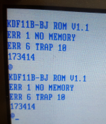
Nice job :->. Can you share the gerber file-set for the adapter, please?Thank you for all your help and comments. Finally, I am able to upgrade M8189 with newer version of ROM with a simple adapter and two M2764A's (200ns). The signal of RS232 can also be seen in oscilloscope. Thank you all again.
I don't recommend round style pins because the sockets will be damaged. Those flat and thin are recommended. Those shown in picture are recycled pins and just the example.Thank you 'cmao' :-}. I don't think that I've ever seen that style of pins; what are they called and where did you acquire them?
ifThank you 'cmao' :-}. I don't think that I've ever seen that style of pins; what are they called and where did you acquire them?
Modern ATX power supplies provide most the current to the 12V supply... check to see how much current yours can provide on the 5V supply. I'm looking at a 400W supply right now that provides 3.3V @ 12A, 5V @ 12A, and 12V @ 28A.
My 225W AXT provides +5V@22A, +3.3V@18A, +12V@16A.Modern ATX power supplies provide most the current to the 12V supply... check to see how much current yours can provide on the 5V supply. I'm looking at a 400W supply right now that provides 3.3V @ 12A, 5V @ 12A, and 12V @ 28A.
No, I meant what I said... modern motherboards take the 12V as the source for the switching regular that provides the massive 1.8V current to the processors...> 5V @ 12A, and 12V @ 28A.
Usually, circuits use much less current on 12V than on 5V.
Maybe you wanted to write
5V @ 28A, and 12V @ 12A?
Even 12V@12A looks a lot. The LSI-11 user manual lists 3.1A for a typical configuration (page 2-4)


Correct, but if he is using a modern ATX supply for his vintage computer, this might be the case... Maybe I missed where the power supply he is using is identified...@jmdhuse
.
> modern motherboards take the 12V as the source for the switching regular that provides the massive 1.8V current to the processors...
That's absolutely true for today, but it's not the way it works on vintage computers.
