Upcoming Events:
- VCF South West - June 14 - 16, Davidson-Gundy Alumni Center at University of Texas at Dallas
- VCF West - Aug 2 - 3, Computer History Museum, Mountain View, CA
- VCF Midwest - Sept 7 - 8 2024, Schaumburg, IL
- VCF SoCal - Mid February 2025, Location TBD, Southern CA
- VCF East - April 2025, Infoage Museum, Wall NJ
-
Please review our updated Terms and Rules here
- Forums
- Companies
- Apple computers, Clones and Descendants
- Later Apple (68k+ based machines - Mac, Lisa, etc)
You are using an out of date browser. It may not display this or other websites correctly.
You should upgrade or use an alternative browser.
You should upgrade or use an alternative browser.
Mac Plus video issue
- Thread starter KenEG
- Start date
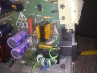
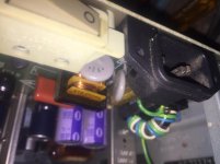
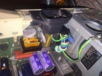
That's definitely an original RIFA capacitor.
I would clip it out / replace it ASAP. Notice how the plastic case is full of tiny little cracks - this is a sure indicator that it won't be long before it fails.
As for replacement you need to get an 0.1uF 220V (or greater, the higher the voltage the better) X rated safety capacitor. Something like this link would be appropriate - however you would need to check the lead spacing is correct.
ngtwolf
Veteran Member
Yup, those gold plastic looking ones are original, and usually you'll see cracks on them as they start to go bad.
i personally don't worry about lead spacing, just bend the leads accordingly.. but to each their own.
i personally don't worry about lead spacing, just bend the leads accordingly.. but to each their own.
KenEG
Experienced Member
OK, I was afraid the X was one of the bad actors. What about the two light purple Y RIFAs? They look OK to me, but this is all new to me.
KenEG
Experienced Member
The light purple one's aren't RIFA's - they are electrolytics.
They are used as smoothing capacitors after the rectifier. If they aren't leaking then they are *probably* ok.
Thanks. They are described as RIFA Y type in some of the repair guides I have been reading.
Hugo Holden
Veteran Member
I just picked up a Mac Plus cheap. No keyboard or mouse. Insides look fairly clean so I turned it on. I get a vertical bar about 1/2 inch wide that does look to have an image in it.
It is very difficult without an image to see to remark on this, can you take a photo of it. The great thing about a visual display on a CRT (that is not completely blacked out) is that is acts like a diagnostic tool (like a scope) for interpreting what and where the fault is located, not only the scanning raster lines and their configuration, but also the way any video data appears in those lines. If you can take two photos of the screen, one photo at normal brightness and another at high CRT brightness. If I could see that I might be able to send you in the right direction.
KenEG
Experienced Member
It is very difficult without an image to see to remark on this, can you take a photo of it. The great thing about a visual display on a CRT (that is not completely blacked out) is that is acts like a diagnostic tool (like a scope) for interpreting what and where the fault is located, not only the scanning raster lines and their configuration, but also the way any video data appears in those lines. If you can take two photos of the screen, one photo at normal brightness and another at high CRT brightness. If I could see that I might be able to send you in the right direction.
I removed the RIFA capacitor and C1 today, so right not just a vertical line. If replacing C1 doesn’t fix it, I will post pictures. I figure me next step if C1 isn’t it is to check voltages.
KenEG
Experienced Member
It looks like the 4.7µF 50V bi-polar capacitors I ordered are in, but they are not the high frequency type. At least they are not advertised as such. The ones that are advertised as being for horizontal deflection haven't even shipped yet. Can the ones I get today be used temporarily to see if that fixes the issue? I would swap it out for the high frequency one when it arrives.
GiGaBiTe
Veteran Member
It looks like the 4.7µF 50V bi-polar capacitors I ordered are in, but they are not the high frequency type. At least they are not advertised as such. The ones that are advertised as being for horizontal deflection haven't even shipped yet. Can the ones I get today be used temporarily to see if that fixes the issue? I would swap it out for the high frequency one when it arrives.
I do not recommend this, you may further damage the analog board.
KenEG
Experienced Member
I do not recommend this, you may further damage the analog board.
Thanks, that is why I asked.
Hugo Holden
Veteran Member
The bipolar special electrolytic capacitors you see in video monitors, in high current or high frequency coupling applications (often coupling capacitors to deflection yokes) are just very low ESR versions of a NP electrolytic, electrically they behave as a just slightly inferior (but not by much) non electrolytic, like a poly cap. If I had an application that required the replacement of that part I always replace with a poly cap. So for something like a 4.7uF 50V NP special part I would replace it with a 4,7uF 100V poly cap, which is a common voltage. Most caps like this have axial leads, so you bend one lead around extend it and insulate it, and/or put heatshrink sleeve over the capacitor body. Usually this will be a small enough part to fit on the pcb where the original bipolar special cap was.The only reason a part like this was not used as they are more expensive at the time.This part will also not fail in the long run, unlike the electrolytic. The other capacitor, you sometimes see in this application labelled as a special is oil filled. They are equally good, if not better than a poly cap and practically never fail.
KenEG
Experienced Member
Are polymer caps bipolar? I get very confused when I search Digi-key or Mouser.
Hugo Holden
Veteran Member
"Poly" is just an abbreviation for a polypropylene or polyester or polystyrene. The former two are the common ones. A capacitor can be made from a number of types of mylar like insulating films. None have any polar properties.
Here is an article that might help:
https://passive-components.eu/what-separates-these-7-types-of-plastic-film-capacitor-dielectrics/
Here is an article that might help:
https://passive-components.eu/what-separates-these-7-types-of-plastic-film-capacitor-dielectrics/
Hugo Holden
Veteran Member
you could use a 50, 63 or 100V 4.7uF part, look at the physical sizes and see what will fit:
https://au.mouser.com/datasheet/2/212/KEM_F3071_A50_AXIAL-1104261.pdf
https://au.mouser.com/datasheet/2/212/KEM_F3071_A50_AXIAL-1104261.pdf
KenEG
Experienced Member
Thanks to both of you. I am just going to wait for the part I have ordered, but am saving the information you provided for future projects.
GiGaBiTe
Veteran Member
This part will also not fail in the long run, unlike the electrolytic
Polypropylene and Polyester film capacitors fail just like any other type of capacitor, it's just the mechanism in which they fail makes them hard to determine if they've failed.
They're highly intolerant of voltage spikes, or being run over their rated voltage. In either case, holes are blown in the insulation layers between the foil and vaporize the foil on both sides of the insulator. This makes them a self healing capacitor at the cost of some capacitance every time such an event happens. Eventually though, so much foil will be blown away that they'll have a significant drop in capacitance and result in circuit failure.
Big Clive has a video of disassembling them to show the effect.
https://www.youtube.com/watch?v=qGc9-ToEiIQ
Hugo Holden
Veteran Member
Polypropylene and Polyester film capacitors fail just like any other type of capacitor, it's just the mechanism in which they fail makes them hard to determine if they've failed.
They're highly intolerant of voltage spikes, or being run over their rated voltage.
Generally, if a polyester cap is not exposed to over voltage (spikes or otherwise in excess of their ratings) it is extremely reliable over very long time frames. On the other hand, capacitors like Rifas, that use a metalized paper film are not. The voltage spike events corrode away the film and their uF value drops with time. Many X2 capacitors suffer this fate. That is why it is folly to use them in circuitry as AC voltage dropping devices, but many companies do it for small appliances. It is also a bad idea to use them in general circuitry for AC coupling or bypass applications. Many have problems such as cracked casings and water absorption too.
Ignoring the fire retardent properties of the X2 type, a polyester cap is far more reliable in the application, provided the voltage rating is high enough. As an experiment , now running a decade, I replaced X2's in a mains voltage dropping application (that lost capacity after 6 months with X2's) with 1500V DC rated polyester types, they are still fine becasuse the mains voltage plus the spikes,doesn't exceed their voltage rating, but it would for example with a direct lightening strike.In early tube gear wax paper caps were used as X2's, they actually seldom gave trouble, because generally they were 1500V DC rated, so were ok on line voltages.
The ideal capacitor though, to replace an X2, is the type used as tuning capacitors in horizontal deflection stages in color sets. These generally have a 1200 to 1500V DC rating and are fine on 240 or 120V mains and they have especially low resistance bonds between the plates and the lead in wires and extremely low ESR. But these, like polyester caps, are not officially rated for any spike suppression activities across the line power even though they would be more reliable than a standard X2. This is because of the fire rating and the fact that they can short circuit, but they should always be fuse protected anyway, and we have all seen Rifa's burn up.
In a coupling application, in a monitor where the peak currents are high, like a deflection yoke coupling capacitor, a polyester cap is better than a bipolar electrolytic and an oil filled capacitor is equally good (but bigger and more expensive). In other circuits where capacitors are involved with substantial circuit currents, such as motor run types, once they were all oil types, now , after going to film types, the industry has noted they degrade and also lose capacity over time in some cases, just like the X2's. But most likely, if they were physical bigger and had thicker insulation with higher voltage ratings they would be ok as my experiments with 1500V rated capacitors & mains power voltages have taught me. The DC ratings of X2 caps are normally lower than 800V and in my opinion not high enough, but everybody wants small physical sized capacitors.
Last edited:
KenEG
Experienced Member
KenEG
Experienced Member
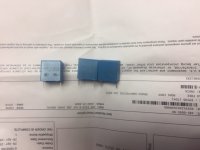
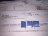
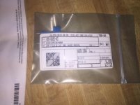
To be clear, these are for the RIFA cap.

