• Please review our updated Terms and Rules here

MAG PMV14AC EGA CRT monitor: is it multisync VGA capable?

retrotomat

Member
Joined
Feb 5, 2023
Messages
15
Location
Paris, France
Hello there!

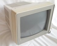
I recently received that monitor that was sold on eBay as a color EGA monitor.

s-l1600 (1).jpg

s-l1600 (2).jpg

I’ve tested with a TTL EGA source on the DB9 port and it works as intended.

I was wondering if it could also work with analog VGA. Maybe through the DB25 port?
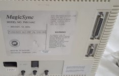
I scoured the web for the pinout but couldn't come up with anything. However I found info that suggest that this may indeed be a multisync monitor. E.g. https://scontent-ams4-1.xx.fbcdn.ne...V9HyG799s3jkOmvVywOjDQwwwCiFymHZQ&oe=6485D37C

There is a thread on Vogons by DaveJustDave that asks the same question about a Gateway 2000 CrystalScan 1024 monitor which is a rebranded version of mine.

I have poked in the DB25 connector with a multimeter in continuity mode just to discover that pin 6 to 10 are ground and that there is no connection at all with DB9 (except pin 1 to GND).
I'm still continuing my investigation.

Does anyone have any information or suggestion before I open it up?
 

Attachments

  • s-l1600 (1).jpg
    s-l1600 (1).jpg
    225.1 KB · Views: 6
  • s-l1600 (2).jpg
    s-l1600 (2).jpg
    179.6 KB · Views: 6
Normally, if a monitor is capable to doing both TTL and analog video, it has some sort of switch to choose between the two. This one does not. Only a "text mode" switch, which will most likely kill the color signal.

"multisync" in this case probably means nothing, as EGA monitors are multisync by design anyway.

One way to find out would be to open the case and check if the pcb has any writings that indicate what signals are on the DB25 port.
 
One of the first common Multisyncs, the original Mitsubishi Diamond Scan, used a 25 pin connector for analog. I suppose it would be too easy if this monitor cloned its pinout.
I checked the AUM-1371A manual (see capture below) and I don't think the pinout is compatible since I already measured pins 6 to 10 of my connector to be GND. And these have different meanings on the Mistubishi (though not related to VGA).
Capture.JPG
Thanks for the usefull link though :) It may come handy later.

Normally, if a monitor is capable to doing both TTL and analog video, it has some sort of switch to choose between the two. This one does not. Only a "text mode" switch, which will most likely kill the color signal.
If it's true that most multisync monitors have a TTL/analog manual switch, some models like the NEC MultiSync 3D don't. That one autodetects the nature of the input signal.
The "text mode" button on mine is indeed used to switch between color and monochrome.
One way to find out would be to open the case and check if the pcb has any writings that indicate what signals are on the DB25 port.
You're right :)
I'm just not super keen to crack a high voltage CRT open (never did that before), which is why I was hoping to find some info first. But I guess I may have no other choice...
 
Last edited:
"multisync" in this case probably means nothing, as EGA monitors are multisync by design anyway.

This monitor is from 1991; EGA was obsolete for four years at this point. Color me skeptical anyone would still be churning out new ones in quantity. And nobody called EGA-only monitors “multisync”; everybody knew what that meant in 1991.

We can only see the back of this monitor, so no switch labeled “analog/digital” doesn’t mean much. Possible alternatives:

  1. “text” means “digital”. MDA/Hercules actually outlived EGA in some niches, and in 1991 that was the most likely use for the digital port.
  2. The analog/digital switch is on the front under the front bezel or on the side.
  3. No switch, but it’s designed to auto detect and gives priority to one of the ports if both are active.
  4. It defaults to digital but the 25 pin port has ”loopback” pins in it to switch it to analog if that is plugged in.
 
There are no other switches than that "text mode" button (plus the brightness, contrast and geometry wheels). I said in my previous post that it was for changing between color and monochrome, but when I tested it again with the EGA on, it just made the image out of sync.
So I'm not so sure now, and alternative 1. might be correct. Or maybe it switches to MDA (not the same frequencies than EGA I think). I haven't tried with a MDA source.
Alternatives 3. and 4. are also possible.

I'll open the monitor in a few days if I cannot find anything else (seems likely...)
 
Last edited:
… FWIW, that model number, “PMV14AC”, searches up as being OEM’ed from MAG, and a couple websites out there list the specs as being able to sync between 15 and 36khz, which means it supports up to 56hz 800x600 or 8514/A-style 1024x768 interlaced. (And it appears on lists of monitors compatible with the Tandy Color Computer 3 and Atari ST, which means it supports analog.)

Unfortunately there’s no manual with the pinouts to be found, like, anywhere.
 
Maybe that text-mode switch is for 15 KHz modes only, or really for MDA. Could be that the monitor has no other way to "detect" an MDA signal.
 
I've finally removed the plastic case.
There are silk screen markings on the PCB that confirm that the DB25 is indeed another video port.

IMG_6551.jpg

We can faintly see the DB9 markings on the right that correspond exactly to EGA.
The info for the DB25 seems to be related to analog video (I suppose RG GG BG are for Red/Green/Blue Grounds, HS VS for Horizontal/Vertical Sync). I'm not sure about SG and DG (other types of GND?). NC is probably unused.
Unfortunately, the arrangement of the labels don't seem to be enough to deduce the exact pinout...

Maybe there are other indications on the other side of the PCB on the solder points that would give the pinout.
The problem is that I can't access that side without dissassembling the inside. That'd require to discharge the tube 😱
Oh well...
 
If those holes were plated through you might be able to do a continuity test between them and the DB-25 pins, but they don't look like they are? Looks like it's a single-sided board?
 
I'm not sure about SG and DG (other types of GND?). NC is probably unused.
DG is digital ground, NC is not connected. No idea what SG is. I could make guesses, but that is of no help.

Getting the pin-out should be easy. Just use a multimeter to check between the holes and the pins of the connector.

At least another question is answered: instead of a switch for TTL/analog, it uses a separate connector.
 
Thank you!

So we have indeed all the components of the VGA DB15 pinout with DG on pin 5 and SG on pin 10. Well, if we except the EDID pins, which are not needed anyway and were introduced later (so it makes sense they're not here).

I had already tried to do continuity tests through these holes but didn't get anything. Maybe my multimeter probes were not thin/sharp enough so I wasn't shorting anything. It looks like there are even smaller holes for HS and VS on this side of the PCB: not sure if I can touch the vias through them.
I'll try again with thinner probes (may have to use needles!). Hopefully I won't need to dissassemble the whole thing :)
 
FWIW, it feels like it might be worth chucking out this question: do you really have a use for analog functionality of this monitor? Specwise it's lousy; if the charts I found were accurate this doesn't even support 800x600@60hz, it's limited to an eye-burning 56hz, and as noted it's missing the ident pins so newer OSes will hate it.

IE, if you just want a color VGA CRT it might be better to just use a different one and keep this one for digital platforms? The main analog use for a monitor like this these days would be for applications that are analog but sub-31khz, IE, for platforms like an Amiga/Atari ST/etc.
 
Given that there are 13 holes and the upper row of the DB25 connector has 13 pins which are directly in front of the holes on the pcb, the signals may be in exactly the same order on the upper row as they are on the pcb. The lower row could be all ground.
 
@Timo W.
Damn, you're probably right!
I wrote in my first post that I had measured pins 6 to 10 (upper row) to GND, and that order matches exactly all the xG of the silk screen (which would mean that all are connected). The bottom row would probably not be connected since I didn't measured its pins to ground.
If that's the case, I've already all the information I need :)

@Eudimorphodon
I wouldn't use this monitor for Pentium or anything newer of course. My main use case is DOS gaming running on a PC/XT up to a 486. I have better TTL and VGA CRTs in my basement but the goal here is to avoid switching between them. I don't have enough room in my office to set more than one retro gaming rig ;)
640x480 would be an absolute maximum. In most case I'll use 320x200 even in VGA since a majority of games of that era uses that resolution.
 
Last edited:
So I made a continuity test on DB25 with the holes on the top of the PCB using a fine needle attached to one of the multimeter probes. I confirm @Timo W. assumption is correct.

At least it is for sure for RGB and the grounds. However I couldn't measure HS and VS since there are no holes for them on this side of the PCB (what appear as tiny ones on my previous photo is actually just dirt).
Instead I found out that the last two pins of the first row of DB25 are both connected with a 135 ohm resistance to HS and VS of the EGA DB9 port respectively. So I assume these are what they seem to be on the analog though I'm not 100% certain.

IMG_6560.jpg

I believe I can now begin some tests by adaptating that new found pinout to a DB15 VGA cable.
Before I do that, do you know if there is a risk of damaging the monitor if the H-Sync and V-Sync signals are not where I think they are?
 
Last edited:
If you mix up the sync signals it should be mostly harmless. They run at several orders of magnitude different speeds so I seriously doubt there is any risk of the monitor doing anything it wouldn’t do if no cable were attached at all.

One telling thing here: if the sync signals really are directly connected between the two ports it’s probably not the best idea in the world to try to leave both ports connected at the same time. That would be a reason for there not being a switch, it’s strictly one port or the other.
 
Instead I found out that the last two pins of the first row of DB25 are both connected with a 135 ohm resistance to HS and VS of the EGA DB9 port respectively.
Makes sense, since the sync signals are the same, but the voltage level is not. The resistor corrects that for the analog input. Quite cleverly made, actually.
 
Back
Top