• Please review our updated Terms and Rules here

Mattel Aquarius Psu

Desperado

Veteran Member
Joined
Nov 25, 2017
Messages
6,827
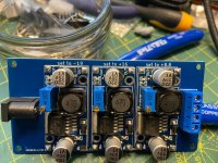
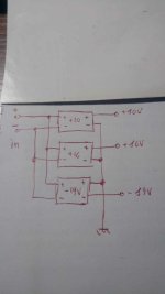
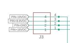
Hi guys, i am here again because i need help for my Aquarius retro computer. The power supply was broken on the primary circuit and i need a New psu. Can someone help me to build a New one please? Maybe with on or two little Dc Dc converter.... These are the voltages that i need. Thanks!
 

Attachments

  • FB_IMG_1705655531073.jpg
    FB_IMG_1705655531073.jpg
    3.5 KB · Views: 4
Are these required to be REGULATED or UNREGULATED DC power rails?

Also, it is not only the VOLTAGE that is important, but also the CURRENT that is drawn by the computer that needs to be known before a recommendation can be made.

I would look at RS, Farnell, Mouser etc. for regulated DC units from MeanWell if you require replacements.

You may also need to think of current protection (e.g. fuses) should a fault develop on the computer board(s) in the future.

What was broken on your original PSU and why can't it be repaired (out of interest)?

Dave
 
Last edited:
Are these required to be REGULATED or UNREGULATED DC power rails?

Also, it is not only the VOLTAGE that is important, but also the CURRENT that is drawn by the computer that needs to be known before a recommendation can be made.

I would look at RS, Farnell, Mouser etc. for regulated DC units from MeanWell if you require replacements.

You may also need to think of current protection (e.g. fuses) should a fault develop on the computer board(s) in the future.

What was broken on your original PSU and why can't it be repaired (out of interest)?

Dave
The transformer cannot be opened because it has no screws but was cast in a single piece. Since it didn't work, I opened it with a dremel and the primary of the transformer had a broken winding. I threw it in the bin a few days ago.
These are the specifics for the Psu:
 

Attachments

  • 1705658402722.jpg
    1.4 MB · Views: 5
As per the info found in this page, the PSU just provides the unregulated voltages for the +12V, +5V and -12V needed internally.

Here someone is replacing its PSU with a new one:

I think you can buy the above here (I'm not related to this seller ;))

...but I'm sure you can mod it to have an internal picoPSU injecting the already regulated voltages. I've seen it done; but can't find where right now...
Thanks but this replacement is out of stock!
Maybe can i build a similar psu with three of this:

I have to understand how they should be connected to also obtain the negative voltage...
 
Think of the power supplies as batteries...

For the +5V and +12V supplies, you wire the negative (-) end of these supplies to 0V/GND/Black.

For the -12V supply, you wire the positive (+) end of this supply to 0V/GND/Black.

This should give you the requisite positive and negative rails relative to 0V.

However, you need to ensure that the outputs of all of the power supplies are isolated from the mains safety earth, otherwise you will accidentally short out the negative supply along with the ensuing black smoke and desparation!

Dave
 
For the -12V supply, you wire the positive (+) end of this supply to 0V/GND/Black.
Hi Dave! Wow nice trick!!
However, you need to ensure that the outputs of all of the power supplies are isolated from the mains safety earth, otherwise you will accidentally short out the negative supply along with the ensuing black smoke and desparation!
How can i do to isolate these outputs?
I saw that the guy who made the power supply left a negative input disconnected...
 

Attachments

  • 274290578_1015551035984504_7004908458005928289_n.jpg
    274290578_1015551035984504_7004908458005928289_n.jpg
    437.2 KB · Views: 4
>>> How can i do to isolate these outputs?

They either should be isolated, or have a user-configurable link.

>>> I saw that the guy who made the power supply left a negative input disconnected...

We don't know how the current power supplies are wired, so we can't assume anything from the unconnected negative input.

Dave
Can be good this schematic?
 

Attachments

  • schema.jpg
    schema.jpg
    44.9 KB · Views: 7
Hmm,

That is 24V 1A and the sum total of the currents of the three unregulated (original) supplies exceed 1A.

I wouldn't, therefore, use that...

It pays to do the sums...

Dave
 
Update:

I built the power supply following the diagram I posted previously and connected the 24V transformer. Unfortunately it doesn't work, maybe the scheme isn't right. The first two cards have an orange LED that flashes while the third (the one with the negative voltage) seems to be off. Maybe 1A are they not enough?
 
You still haven't identified to me the part number for the low voltage regulators you are using and whether the output is isolated from the input or not.

If not, it is highly likely that the negative output will not work.

Either way, unless we have the documentation for the modules, we have no idea what a flashing orange LED means...

This is the more likely scenario than the 1A current at this point in time. Get the design/theory correct BEFORE buying the bits and connecting them up...

Dave
I have these voltage regs. Dave but i don t know if the negative output it Is isolated or not...
 

Attachments

  • 1705765829241..jpg
    1705765829241..jpg
    1 MB · Views: 1
The voltage regulator TYPE is not important.

The manufacturer and part number of the MODULE itself is.

I told you in post #8 that if the negative output is not isolated it will not work...

Dave
 
Back
Top