• Please review our updated Terms and Rules here

Me and my pdp-8/L

Many if not most EPROM socket based chip programmers also have the ability to do test on 74xx devices.
Like this: https://www.aliexpress.us/item/3256804418791341.html one of the TL866 clones. Amazing amount of stuff for $15.
I use my EEtools TopMaxII programmer as a 74XX tester as well as for DRAM and SRAM devices. Also for testing 8641s etc since you can write your own tests too.
 
Gwiley has pages about his Arduino-based version, and can probably steer you there. There's also the USB/Windows solution from M_thompson. The tester has come up in various threads here. I don't have a list to hand, so I'd suggest ufint the "Search" thingy in the corner with "flip chip tester" or the like. (I don't envy you trying to read all this on your iPhone, though.)
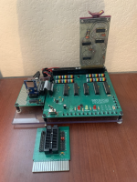
As Vince mentioned, there's an easily buildable Flip Chip tester documented here: https://github.com/G-Wiley/Flip_Chip_Test_System
and a zif socket adapter here that fits into the flip chip tester: https://github.com/G-Wiley/IC_Test_Jig

I began with the work by Warren Stearns, Michael Thompson, and Vince and adapted it for the small and inexpensive ESP32. To test boards it does require a computer connected to the USB port on the ESP32 but no internet connection is required to run tests. You will need an internet connection, of course, to download the files from github and to load the Arduino software into the ESP32. Maybe take your computer to a Starbucks and load up what you need from github and the Arduino installer.

All of the test vector files are stored on a microSD card that's connected to the tester controller. You'll need a computer that runs a terminal emulator to enter test commands and observe results. Also will need a +5V power supply to power the tester and board under test.
There's an extensive library of Flip Chip board test vector files on Vince's website which is linked from my github,
and some additional Flip Chip test vector files are here: https://github.com/G-Wiley/Flip_Chip_test_procedures_and_vectors.

I may also be from a similar decade and grew up in Gridley, so a well-seasoned north-valley person can do this :)
I might even have an extra tester pcb and tester controller pcb in boxes under my desk, need to check.

Tester board with test controller to the left mounted on an acrylic square. M160 Flip Chip is plugged into the tester. IC Test Jig is in the foreground.
(tap the image to enlarge it)
1701984498913.png
 
Did you look at my repair thread when I fixed both my pdp8/L's? I ordered one of those 74xxx chip testers with a clip on cable and used that to fix the major registers, M113's, the 4,6,and 8 input NAND gate boards and the flip flop boards by testing the chips in circuit. Makes a MASSIVE difference in the resulting system, then you can start testing knowing that something is good.....

C
 
As Vince mentioned, there's an easily buildable Flip Chip tester documented here: https://github.com/G-Wiley/Flip_Chip_Test_System
and a zif socket adapter here that fits into the flip chip tester: https://github.com/G-Wiley/IC_Test_Jig

I began with the work by Warren Stearns, Michael Thompson, and Vince and adapted it for the small and inexpensive ESP32. To test boards it does require a computer connected to the USB port on the ESP32 but no internet connection is required to run tests. You will need an internet connection, of course, to download the files from github and to load the Arduino software into the ESP32. Maybe take your computer to a Starbucks and load up what you need from github and the Arduino installer.

All of the test vector files are stored on a microSD card that's connected to the tester controller. You'll need a computer that runs a terminal emulator to enter test commands and observe results. Also will need a +5V power supply to power the tester and board under test.
There's an extensive library of Flip Chip board test vector files on Vince's website which is linked from my github,
and some additional Flip Chip test vector files are here: https://github.com/G-Wiley/Flip_Chip_test_procedures_and_vectors.

I may also be from a similar decade and grew up in Gridley, so a well-seasoned north-valley person can do this :)
I might even have an extra tester pcb and tester controller pcb in boxes under my desk, need to check.

Tester board with test controller to the left mounted on an acrylic square. M160 Flip Chip is plugged into the tester. IC Test Jig is in the foreground.
(tap the image to enlarge it)
View attachment 1269350
If you are from Gridley, then we just may know each other.

Do you know anything about a Christmas tree farm 9 miles north of Paradise?

I would love to take a good look at that tester.
Did you look at my repair thread when I fixed both my pdp8/L's? I ordered one of those 74xxx chip testers with a clip on cable and used that to fix the major registers, M113's, the 4,6,and 8 input NAND gate boards and the flip flop boards by testing the chips in circuit. Makes a MASSIVE difference in the resulting system, then you can start testing knowing that something is good.....

C
I think I did, but I’ll check again.
I cable and clip is now sitting in the post office. Should have it by the weekend.
 
Ok. To sum it up, I looked at the systems as a series of blocks. You have to fix the switch panel and lights first and make sure they are working because that's the foundation into the system. Next is the manual clock board and supporting boards for the general registers (controls the load address, deposit, examine functions) then the general register boards (and their flip flops). Once that's working and you can actually "talk" to the system you can start working on the memory system and instructions (put something into memory, read it, addressing) then the operator instructions, ending with the IO system.

Each system builds on and depends on the operation of things before it. But testing things like the M11x series boards and the basic flip flop boards ensures that SOMETHING will be somewhat reliable in your quest. And for that a simple 7400 chip tester with clip is a godsend.
 
Ok, switches and lights work. Got that. Manual timing board… that’s the M700 board. I believe it is working. I also know that I have 4 M220 major registers working.
The last two has issues.

I have tried to find your thread on fixing your 8/L but was unable to locate it. Link maybe?
 
Yes, the power supply is working and is correct.
The second power supply came to me in a zillion peices and a very corroded frame. It’s a mess.
Looks like it was robbed for parts as the fuse holders, rfi is missing. Also a weird looking rectifier appears to be missing as well.
 
A small update and a question that’s probably going to cause you all to say something like WTH ???

I’m waiting for a tool to help me on my 8/L project, nothing new here.
Also work at the arcade piling up.

The other day, I ran into an old photo of a desktop computer with a Flexowriter. It’s a univac built for the Navy, I think.
So, my stupid thought was to make or convert the 8/L from the box into a new cabinet that looks like this univac trainer.
The backplanes will remain the same as well as the power supply.
But the control panel will be rebuilt with all lights and switches along an extra row of lamps for the program counter and I/O.

See picture of my stupid idea.
 

Attachments

  • IMG_6242.png
    IMG_6242.png
    838.2 KB · Views: 30
Does anyone have a test program to help diagnose problems for the pdp-8L ?

Paper tape, hex, octal or Binary.

Any help would be greatly appreciated.

Thank you
 
The diags you are looking for would be the maindec-8l and the maindec-8i programs. The L is a subset of the I. The maintenance manuals for each model have a list of the diags to be run after installation. The first one you should run is called Instruction Test 1 which has a DEC designation of MAINDEC-8I-D01C-PB for the binary of the paper tape for the 8/I I don't know if there was a more specific version of this for the L. I don't have an L so I have not looked for diags specific for that model. I didn't see one in a quick search but that doesn't mean it doesn't exist. Vince has a good collection of the maindecs on his site. Here is a link to that section. https://so-much-stuff.com/pdp8/software/dec.php#maindec

You can also run the diags from the Straight 8 if you can't find the specific one for the L or I. For the most part there were only tiny changes made to the diags from the original Straight 8 versions. And probably those were based on the PDP-5 diags.

Instruction test 1 has almost no JMP instructions. It first ensures that HLT works and then sets up test conditions and conditionally skips over HLT instructions. You look at the source listing to see exactly what was being tested for the HLT at the address where it halts. It tries to test instructions before it uses them in later tests so it starts simple and builds up to progressively more complicated tests. It does not test JMP, JMS, DCA, IOT or ISZ instructions and uses almost none of those. I think there is one JMP at the very end and one used after it rings the bell to wait for the character to finish being sent. And the only IOT is the sending of the BELL character to indicate pass complete. I think there might be a couple of DCA used to determine if enough passes have occurred to ring the bell.

Best Wishes and I hope your machine comes up easily.
 
Thanks for the information.
I must be spoiled, because I am an Arcade tech, our manuals have a Diagnostic menu. It would that the 8/L does not. Bummer Dude.
 
Thanks for the information.
I must be spoiled, because I am an Arcade tech, our manuals have a Diagnostic menu. It would that the 8/L does not. Bummer Dude.
Have to remember that this machine was introduced in 1968, and things were quite primitive back then, compared to how things were done a decade or two or three later.

@czunit commented about how he brought up an 8/L, actually two of them. https://forum.vcfed.org/index.php?threads/me-and-my-pdp-8-l.1245567/post-1352902

I used a similar but slightly different approach.
  1. restored the big electrolytic caps in the power supply
  2. Verified all supply voltages under load while disconnected from the rest of the machine. I disconnected and shorted around the EMI "Y" capacitors. Just didn't want to risk having them explode.
  3. like czunit, pulled out the front panel board and manually verified every light and switch. There was lots of cleaning required inside the switches. There were many bad bulbs. When I pulled out a bad bulb I soldered in two pins from a machine contact IC socket (removed from the socket plastic) to the bulb could be easily replaced in the future).
  4. Tested nearly every logic card on the variant of the Stearns Flip Chip tester.
  5. Debugged writing and reading memory using the front panel switches and lights. This uses timing created by the M700 Manual Timing Generator in slots C3 and D3.
  6. At this point I started attempting to run code but first they were simple things such as an AC lights increment program and a Hello World program to test the serial port. You'll need a working serial port to run maindecs tests.
 
Vince has a good collection of the maindecs on his site. Here is a link to that section. https://so-much-stuff.com/pdp8/software/dec.php#maindec
As part of my SIMH testing, I've looked into rounding up the acceptance tests for various models. I show the 8/L acceptance test as being:
maindec-8i-d01c Instruction Test 1
maindec-8i-d02b Instruction Test 2
maindec-08-d02b Instruction Test 2b
maindec-08-d04b Random JMP Test
maindec-08-d05b Random JMP-JMS Test
maindec-08-d07b Random ISZ Test
maindec-08-d1b0 Memory Address Test (low and high binaries are b1, b2)
maindec-08-d1l0 Memory Checkerboard (low and high binaries are l1, l2)

Those are all available on the above linked page or here:
You might have to scroll the table a bit to find the individual files you want.

Getting the files loaded into your 8/L will be the next challenge. As you've noted, there's no ROM or BIOS to help. OTOH, the core is non-volatile until it gets clobbered.

Vince
 
After memory seems to work here are simple programs you can toggle in from the front panel. Didn't check thread to see if already discussed. Note that these are for 8/E. BSW doesn't work on your machine so stop test at BSW.

Console print test and echo test are good for checking serial port. Can then either try RIM and BIN to load diags or other toggle in programs.

http://www.pdp8online.com/pdp8cgi/query_docs/tifftopdf.pl/pdp8docs/toggle_in_programs.pdf

maindec-801-1-pm is RIM format so if BIN won't run you can try it with RIM.
 
Just a small update on my pdp-8/L.
Yea, it’s been a while, but I got the last part for my chip tester. And it worked great until I broke a pin on the test clip.
But I did get to test all the M111 flip chips. Wow!! There were 7 of these with my 8/L. 2 tested ok, 5 were bad. Out of that 5, 11 of those DM7400 had bad gates.
But then, I broke a pin on the test clip. Now I need to order a new one.
 
Back
Top