gwiley
Experienced Member
6 months ago I built a small Omnibus backplane. For a long time I didn’t have a PDP-8/E/F/M chassis with backplane and power supply and wanted to get a system running using my Omnibus board collection.
I’ve had a number of requests to release the design files of this mini backplane to use it for debugging and to build a system without a real chassis+backplane+power supply, so I was thinking to make the design files available on my github. There were some issues with the first mini backplane version which have been fixed recently but I’ve not yet built the updated version (v2). Before calling the v2 design “done” it would be good to get feedback from experts here to see if there’s anything that should be added or modified.
So, the following is a short description so people can comment. I’ll post a more detailed description with design files and component sourcing on github.
The schematic is in the attached pdf. Circuit-wise, there’s not much here, just connectors for nine Omnibus slots, a Power OK circuit (copy from the H740 power supply), and power input terminals.
The board design is shown in the following two images (top & bottom). The layout considerations were primarily to minimize voltage drop in the +5V net. The -15V was also fairly robust but I realized later that not much core memory would be installed, so priority was given to have a solid +5V rail.


The first version was designed for 2 oz copper. But to reduce the cost, v2 can be fabricated using 1 oz copper and two AWG 14 jumpers are included to distribute +5V across the long dimension of the board. There’s a voltage drop analysis that I’ll upload to github, or if anyone is curious I can share it here too.
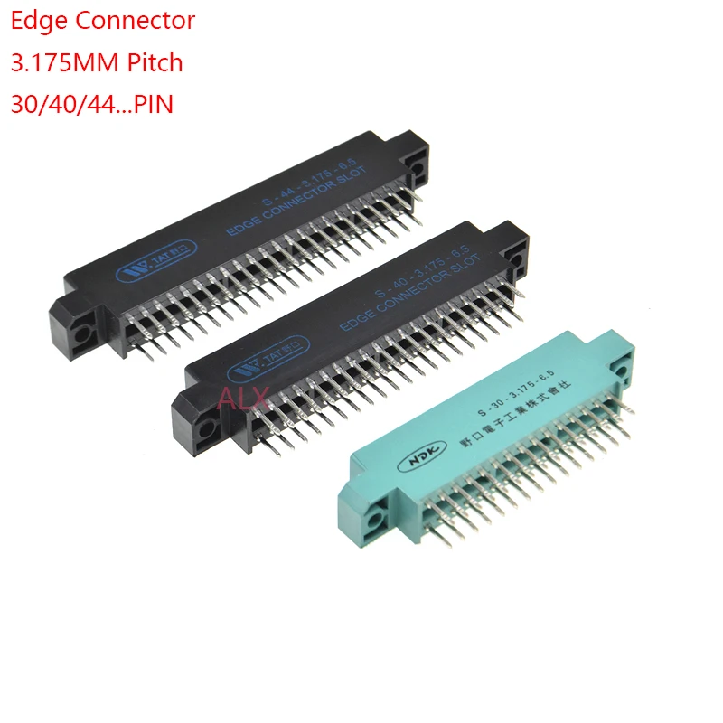
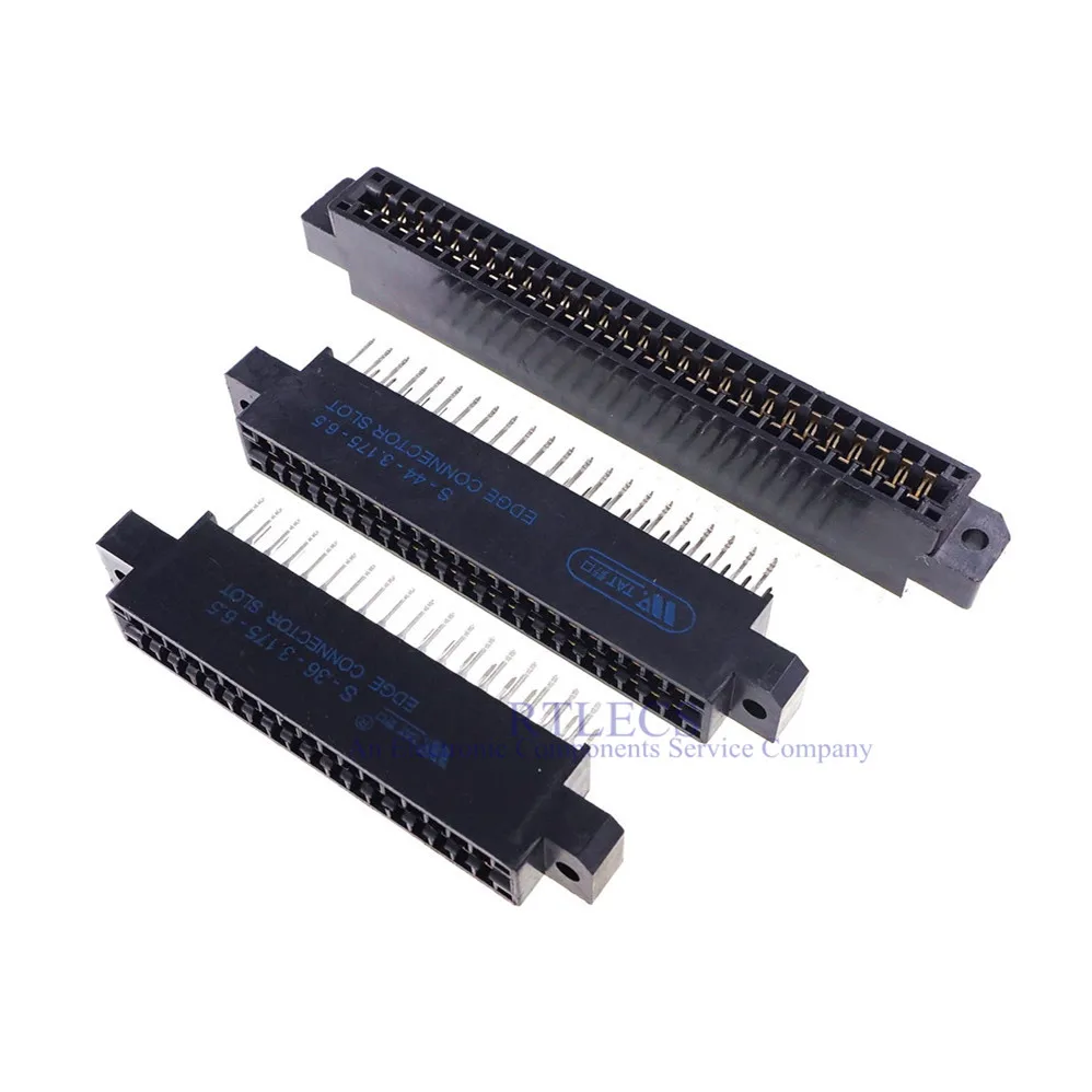
The connectors with 0.125" (3.175 mm) contact spacing available from AliExpress aren't the nice deep slot connectors as on a real DEC backplane. They're more shallow and allow a wider "tounge" (the part with the gold fingers). I made a pair of acrylic strips with a kerf every ½ inch that holds the boards a little more steady. To make the plug-in boards align well it's necessary to use either dual 40 or dual 43 pin connectors, cut of both sides, remove some pins and install shims between the A and B, and between C and D. I learned this trick from the Douglas Electronics Omnibus module extender. The shim is a very simple piece designed using Microsoft 3D builder. I had some shims 3D printed and they fit nicely. I can share the STL file. There are two sources for for the same connector (the 2x40 or 2x43, again, some modifications are required):
 www.aliexpress.com
 www.aliexpress.com
I’ve had a number of requests to release the design files of this mini backplane to use it for debugging and to build a system without a real chassis+backplane+power supply, so I was thinking to make the design files available on my github. There were some issues with the first mini backplane version which have been fixed recently but I’ve not yet built the updated version (v2). Before calling the v2 design “done” it would be good to get feedback from experts here to see if there’s anything that should be added or modified.
So, the following is a short description so people can comment. I’ll post a more detailed description with design files and component sourcing on github.
The schematic is in the attached pdf. Circuit-wise, there’s not much here, just connectors for nine Omnibus slots, a Power OK circuit (copy from the H740 power supply), and power input terminals.
The board design is shown in the following two images (top & bottom). The layout considerations were primarily to minimize voltage drop in the +5V net. The -15V was also fairly robust but I realized later that not much core memory would be installed, so priority was given to have a solid +5V rail.
The first version was designed for 2 oz copper. But to reduce the cost, v2 can be fabricated using 1 oz copper and two AWG 14 jumpers are included to distribute +5V across the long dimension of the board. There’s a voltage drop analysis that I’ll upload to github, or if anyone is curious I can share it here too.
The connectors with 0.125" (3.175 mm) contact spacing available from AliExpress aren't the nice deep slot connectors as on a real DEC backplane. They're more shallow and allow a wider "tounge" (the part with the gold fingers). I made a pair of acrylic strips with a kerf every ½ inch that holds the boards a little more steady. To make the plug-in boards align well it's necessary to use either dual 40 or dual 43 pin connectors, cut of both sides, remove some pins and install shims between the A and B, and between C and D. I learned this trick from the Douglas Electronics Omnibus module extender. The shim is a very simple piece designed using Microsoft 3D builder. I had some shims 3D printed and they fit nicely. I can share the STL file. There are two sources for for the same connector (the 2x40 or 2x43, again, some modifications are required):
2.44US $ 6% OFF|1pcs Edge Card Connector Slot 3.175 Mm Pitch 30/40/44/56/60/72/80/86/100 Pin Pcb Gold Finger Socket Through Holes - Connectors - AliExpress
Smarter Shopping, Better Living! Aliexpress.com
15.2US $ 5% OFF|5pcs Edge Connector Slot 3.175 Mm Pitch 30 36 40 44 56 60 72 80 86 100 Pin Pcb Gold Finger Board Socket Through Holes Flange - Connectors - AliExpress
Smarter Shopping, Better Living! Aliexpress.com


") .
.