• Please review our updated Terms and Rules here

Miniscribe 3425 Track Zero Sensor Issue

Securix

Experienced Member
Joined
Oct 7, 2009
Messages
196
Location
New Joizey, USA
Another computer I was planning to bring to VCF 9.1 is giving me a grief.

I got an Altos 886 a few years back that I managed to get booted up nicely to Xenix when I first got it. Played around with it for a bit exploring all the stuff left on it by its previous owners and then shut it down and put it in storage. Just fired it back up and it won't boot anymore.

The hard disk, a Miniscribe 3425 20MB, powers on and spins up, but I can hear the head assembly not moving around as I would expect.

I finally pulled the unit out of the machine and powered it up while observing the front LED and noticed it's flashing an error code pattern.

The code is "solid - flash - flash - flash," which based on the codes in this manual (though not for the exact model - I'm assuming the basic codes would be common among these early models) translates to 1000 or Code 8 - Could not Uncover Track Zero Sensor.

Reluctantly I pulled the cover off and took a look inside. I don't immediately see any sensor inside the unit, but I do see this small sensor bolted to the side of the head actuator motor (outside the platter casing) though which passes the small interruptor arm as the head motor spins about.

miniscribe-3425-actuator.jpg


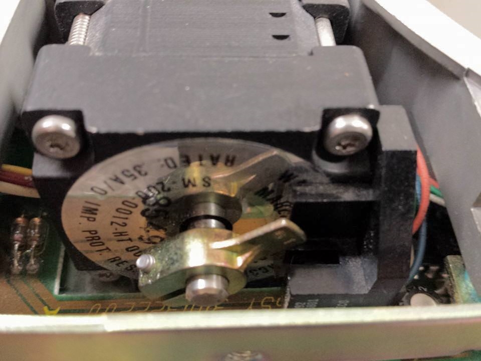
What I have noticed is that manually spinning the arm (powered off, of course) and moving the head assembly to the outermost edge of the platter, the arm will position itself exactly through the sensor. Based on what I read, that should indicate track zero. But when the drive spins up and gets to rotational speed, the arm only moves counterclockwise about 10 degrees, then stops, and the error code begins flashing. That leads me to think that if indeed the error code I'm reading is correct, it might indicate a track zero sensor issue, that maybe the sensor is either dirty or faulty. I've tried cleaning it out (assuming its an optical sensor) by sliding a bit of damp cloth through the sensor, but that did not help.

The sensor itself looks like its bolted to the side of the motor housing and the wiring harness plugs into the logic board so it shouldn't be too hard to replace assuming that's the issue and assuming i can find a working replacement.

Need some advice on whether I'm on the right "track" or if the issue could be something else entirely.

Thanks.
 
I don't immediately see any sensor inside the unit, but I do see this small sensor bolted to the side of the head actuator motor (outside the platter casing) though which passes the small interruptor arm as the head motor spins about.
Yes, that is the track 0 sensor.

I'm assuming the basic codes would be common among these early models) translates to 1000 or Code 8 - Could not Uncover Track Zero Sensor.
But when the drive spins up and gets to rotational speed, the arm only moves counterclockwise about 10 degrees, then stops, and the error code begins flashing.
That 'about 10 degrees' behaviour is what I would expect for a situation where the CPU on the logic board always sees an active 'heads on track 0' signal (whether that be because of a faulty sensor, or because of faulty associated electronics on the logic board, or other).

I imagine that part of the programming for the drive's self test is:
* If 'heads on track 0' signal is active (i.e. sensor covered), then step the stepper by about 10 degrees (enough for stepper arm to move out of sensor), and then verify that the 'heads on track 0' signal has become inactive. If it did not go inactive, issue code 8.

and the wiring harness plugs into the logic board
Perhaps the sensor's connector has developed a bad connection with the logic board. Have you tried reseating the connector (a few times)?
 
A long time ago I worked in product support for company that had a 20MB hard drive product that had a failure issue with the track zero sensor. It might have been with the same Miniscribe 3425 hard drive. I know it flashed a specific error code on power up which identified the problem. In the case of the failures we experienced it was almost always due to the interrupter flag rotating out of position on the shaft on which it is mounted. If that was the cause it could be corrected by rotating the interrupt flag back into the correct position.

The procedure for doing that was to loosen the set screw on the interrupter flag while the drive was powered off. The set screw needed to be loose enough that manually rotating the interrupter flag did not rotate the shaft. Then power on the drive with a short across a pair of test jumper pins on the drive logic board. I believe that must have caused the drive to seek to what it thought was track zero based on information other than the track zero sensor. Then the interrupter flag would be manually rotated back into the correct position. In that special power up mode the hard drive LED indicated the current state of the track zero sensor instead of flashing the error code. The interrupter flag would be manually rotated into or out of the track zero sensor until it was in the position where it was just at the threshold of the LED turning on or off. Then the set screw would be tightened down again (carefully, without rotating the shaft) and the drive power cycled up again without the test jumper. If that solved the problem the set screw would be secured with Loctite.

That was over 25 years ago. I don't remember how many jumper pins there were on the hard drive logic board and if it was obvious which were the pair of test jumpers that needed to be shorted to put the drive into the special power up mode.
 
Last edited:
That 'about 10 degrees' behaviour is what I would expect for a situation where the CPU on the logic board always sees an active 'heads on track 0' signal (whether that be because of a faulty sensor, or because of faulty associated electronics on the logic board, or other).

I imagine that part of the programming for the drive's self test is:
* If 'heads on track 0' signal is active (i.e. sensor covered), then step the stepper by about 10 degrees (enough for stepper arm to move out of sensor), and then verify that the 'heads on track 0' signal has become inactive. If it did not go inactive, issue code 8.

Perhaps the sensor's connector has developed a bad connection with the logic board. Have you tried reseating the connector (a few times)?

Thanks for all the help so far everyone.

I've wiggled the connector but not completely reseated it. I'll give that a try as well.

Also, though i don't have a scope, I do have a multimeter I could use to test the sensor's signal, for example when the flag is covering the sensor and when it's clear of the sensor. I imagine the output voltage would change depending on whether the sensor was covered or open. And there's only four wires or so, so it should be easy to figure out which is the emitter side and receiver side, assuming it's a photosensor. If I could figure that out, it could narrow down whether it's the sensor or something on the logic board.

I did find this short document that has a little more info about the test settings (in this case, DIP switches rather than jumpers) and is specific to the 3425. Unfortunately, it doesn't really go deep into how to use the test settings or any signal/voltage levels or pinouts. It would be great to have a real service manual from which to reference the pinouts and expected signal levels. There's very little to go by on these old units so it'd be great if anyone had access to anything better.

Thanks!

-Anthony
 
Last edited:
Those Miniscribe drives are about the most horrible things to exist. Once they develop ANY sort of problem they're usually dead for good.
 
Also, though i don't have a scope, I do have a multimeter I could use to test the sensor's signal, for example when the flag is covering the sensor and when it's clear of the sensor. I imagine the output voltage would change depending on whether the sensor was covered or open. And there's only four wires or so, so it should be easy to figure out which is the emitter side and receiver side, assuming it's a photosensor.
On the receiver side, expect the DC voltage on one of the pins to change significantly. Whether the voltage goes up or down, and the two different voltage levels, will depend on how the designers have engineered the sensor into the overall track 0 sensing circuitry on the logic card.

If you do not see a voltage change, then consider:
* Poor connection of sensor to logic board
* Faulty sensor - LED (emitter) side
* Faulty sensor - Photodiode (receiver) side
* Faulty logic board (in the track 0 sensing circuitry: component failure / bad solder joint / open trace)
 
Those Miniscribe drives are about the most horrible things to exist. Once they develop ANY sort of problem they're usually dead for good.

So anyone with any experience working with Altos 886 series machines know if they were capable of recognizing and using larger hard drives, such as an 80MB unit, which I may have laying around? I figure worse comes to worse I can make new install floppies from the image files that are out there, reinstall, and just cut my losses.

On the other hand I was able to get some readings off the track zero sensor. As the drive is powered up I took readings across the detector and got about 0.4v that kind of fluctuated a bit. As soon as the flag rotated up 10 degrees, the reading shot up to 1.180v and remained stable, which I take to mean the logic board successfully tries to activate and read the sensor. I rotated the flag to cover the sensor but the reading remained 1.180v. I assume logically, if the drive is spitting out the error code that it can't uncover the sensor, that the 1.180v I'm reading is being read as sensor covered, and it should theoretically be somewhere around 5v if it were working properly uncovered. So I'm thinking it may be either a dirty or faulty sensor.

I can remove the sensor and try to clean it a bit and try again (reseating the connector didn't help.) It requires removing the logic board and the thin mounting braces but shouldn't be too hard. The sensor does have a part number that I tried to Google but came up empty. Easiest thing to do is swap it with a sensor from a working 3425 or just replace the whole drive and reload Xenix as I mentioned.
 
On the other hand I was able to get some readings off the track zero sensor. As the drive is powered up I took readings across the detector and got about 0.4v that kind of fluctuated a bit. As soon as the flag rotated up 10 degrees, the reading shot up to 1.180v and remained stable, which I take to mean the logic board successfully tries to activate and read the sensor. I rotated the flag to cover the sensor but the reading remained 1.180v. I assume logically, if the drive is spitting out the error code that it can't uncover the sensor, that the 1.180v I'm reading is being read as sensor covered, and it should theoretically be somewhere around 5v if it were working properly uncovered.
Again, the voltage levels will depend on the circuitry used, as will be the signal direction. But a change in voltage should happen when you manually move the flag in and out of the sensor.

So I'm thinking it may be either a dirty or faulty sensor.
It is only a possibility.

One example of a few: A fault in the logic board might result in the sensor's LED not being supplied with the required current (no current at all, or inadequate current). The receive side of the sensor would never sense LED light (i.e. the same symptom if the flag never moved out of a functional sensor).

If it was my drive, I would be tracing out the 'track zero' circuitry on the logic board (which is not much at all) and then together with the sensor specs, calculating the approximate voltages I should expect to see.
 
Don't throw it out yet!
Could it be that the stepper motor itself is gummed up and can't move properly? I've dealt with many of these drives and that is usually the issue with this error code. They are much more repairable than you might think. It is possible to designate a new track 0 when the original is completely worn out, simply by moving the interruptor. I have done this on more than one Miniscribe that were considered impossible cases because low-level formatting could not restore track 0.
Anyway, to fix the interruptor-can't-move problem, I have simply rotated it by hand (carefully), and sometimes added lubricant directly on the shaft going into the motor. I think I would recommend clock oil, but WD-40 works too. ;)
 
It is possible to designate a new track 0 when the original is completely worn out, simply by moving the interruptor. I have done this on more than one Miniscribe that were considered impossible cases because low-level formatting could not restore track 0.
Could you be more specific about this? I have some drives (Miniscribe and others) that I might be able to revive if I could designate a new track 0. I've already attempted one method discussed here at length in another thread but that was unsuccessful. If you've got another method I'd be interested in giving it a shot.
 
I'm not sure what method you tried, so mine might be the same. All I did was loosen the set screw, and push the interrupter a hair farther than it is supposed to go. It has been a while, but I think you can go in either direction. If you go too far it will fail, as it tries to seek farther than it can, or track 0 ends up beyond the reach of the stepper.

By the way, if you have any of the 8425/8438 twins that you are unable to revive, I would gladly buy them off you as I could use a couple of logic boards. :)
 
By the way, if you have any of the 8425/8438 twins that you are unable to revive, I would gladly buy them off you as I could use a couple of logic boards. :)
Send me a PM with your email addy for my files; I've got at least a half dozen that were all working years ago, but who knows what I'll find when I test them again one of these days.
 
A long time ago I worked in product support for company that had a 20MB hard drive product that had a failure issue with the track zero sensor. It might have been with the same Miniscribe 3425 hard drive. I know it flashed a specific error code on power up which identified the problem. In the case of the failures we experienced it was almost always due to the interrupter flag rotating out of position on the shaft on which it is mounted. If that was the cause it could be corrected by rotating the interrupt flag back into the correct position.

The procedure for doing that was to loosen the set screw on the interrupter flag while the drive was powered off. The set screw needed to be loose enough that manually rotating the interrupter flag did not rotate the shaft. Then power on the drive with a short across a pair of test jumper pins on the drive logic board. I believe that must have caused the drive to seek to what it thought was track zero based on information other than the track zero sensor. Then the interrupter flag would be manually rotated back into the correct position. In that special power up mode the hard drive LED indicated the current state of the track zero sensor instead of flashing the error code. The interrupter flag would be manually rotated into or out of the track zero sensor until it was in the position where it was just at the threshold of the LED turning on or off. Then the set screw would be tightened down again (carefully, without rotating the shaft) and the drive power cycled up again without the test jumper. If that solved the problem the set screw would be secured with Loctite.

That was over 25 years ago. I don't remember how many jumper pins there were on the hard drive logic board and if it was obvious which were the pair of test jumpers that needed to be shorted to put the drive into the special power up mode.

I've been trying this method, so far with no luck but I'm only just started, but have been at least able to get into the mode you mention. Turning off SW3 on the DIP of a 3425 causes it to turn on the LED whenever the sensor is covered (in the specs this is indicated as a "factory use only" mode). Not sure about the logical seek part, but the LED portion corresponds to what you posted here.
 
Back
Top