• Please review our updated Terms and Rules here

MiniScribe 8438 flashing error code

I have a MiniScribe 8450. There is no letter designation after the number.
It is the 3.5" 1/2 height drive. I am assuming it is an 8 bit drive.
Is that the same as 8450F and <or> 8450A? You guys seem to know what this really is.
A YouTube video said certain drives can be RLL or MFM. Maybe this can be if the letter
at the end is the same thing for A , F and nothing?
Seems the 8450XT = 771 cyl. and 8450AT = 805 cyl. Is there a chart of all 8450's somewhere with all specs?
I have a 8bit DTC-5150CR control card that can do MFM only but standard BIOs doesn't show the HD 8450 size.
I would have to get the DTC-5160CR card to do DLL. I suppose that is where the 16kbit BIOS can be found, maybe?
It has only an 8 Kbit BIOS and the specs claim it needs a 16 Kbit BIOS to set the parameters manually with "special parameters".
Below Wayback specs right from Maxor/MiniScribe say it is 8450A that can be DLL or MFM but it is a 16 bit IDE interface.
I believe IDE means it is a newer drive than what I have with the single IDE cable rather than the two separate control ribbon and data ribbon.
The 8450F will be designated with an "F" at the end of the model number sticker. These drives get a low impedance stepper which improves access times somewhat. I believe the PCB is identical between the two.
The "A" and "X" designations are used for the IDE version - X being 8-bit and A being the more common 16-bit. There is also an "S" version which uses SCSI-SE.

With no letters at all, your drive is a bog standard 8450, which uses the ST-412 interface. This appears to the user as two edge connectors, one larger than the other. They are 34 and 20 pins, respectively. In essence, this drive is "dumb," in that is has no influence over the system whatsoever. Your controller could be writing one bit per track or be addressing only 615 of those cylinders and 2 of those heads and the drive would never know or care.
The 8450 is "RLL certified" which implies that it's media is capable of reliably storing data at 7.5 megabits, or as it will appear to your operating system, 26 different 512 byte sectors per track. Your controller is a more common unit which is only capable of 5 megabit, or 17 sectors per track, which was the standard at the time. The drive does not know or care about this - You can still use the drive, but you will lose around 33% of it's capacity due to this mismatch.

The 8450A and X are always RLL internally - As in, their onboard logic always operates at 7.5 megabits, but many PC compatible computers were still built with the expectation that every drive had 17 sectors. Thus, a drive which presents itself to the machine as having "26 sectors" might cause issues. As a result, many IDE drives implement sector translation which allows them to appear as if they had different physical geometry and report only 17 sectors for compatibility. Because your drive is not an A or X variant, you do not need to worry about this.

The BIOS will not make much of a difference to sector count - That is hard limited by the speed of the rest of the hardware onboard the controller. Because these drives are dumb, you can simply pick a different geometry which is "close enough" but less than the actual geometry of your unit. Because you have 771 addressable cylinders, the closest standards are probably the typical 615/4/17 used by many 20MB disk drives of the era (which may be represented as the Miniscribe 3425 or 8425, Seagate ST-225, NEC D5126, etc) or something close with 733 cylinders, which was a common number for many voice coil drives. I don't think many had 4 heads, though, so you would be losing an entire surface, which is undesirable. Typically they had odd numbers of heads.

tl;dr You probably have the standard 8450. Don't worry about your controller, you will miss out on some storage due to the mismatch, which will be amplified if you are limited to "standard" geometries. If you want to fully utilize this drive, it would be in your interest to put it in an AT with a "real" RLL controller like the DTC 7287 instead.
 
Thank you for that. Card I have came with BIOS BXD07 which is 8k DIP28 BIOS. It comes on a socket as well. I was wondering if I find a 16k BIOS from another card could I just plug it in and make it work for the jumper that allows for what they call " special settings "? Specs claim you need 16k BIOS so pin point the drive size for it's built in low level format.
On the the other hand Speed Store program allows for picking out your specific drive size for formatting and partitioning. Maybe changing the card BIOS isn't necessary for the DEBUG G=C800:5 will just get the drive to communicate with a low level format then SSTOR can dial it in for full capacity?
 
No, as mentioned before, SpeedStor is not a god and if your controller is limited to a certain set of geometries, nothing SpeedStor can do will fix that.
 
Thank you for that. Card I have came with BIOS BXD07 which is 8k DIP28 BIOS. It comes on a socket as well. I was wondering if I find a 16k BIOS from another card could I just plug it in and make it work for the jumper that allows for what they call " special settings "? Specs claim you need 16k BIOS so pin point the drive size for it's built in low level format.
You asked something related elsewhere [here]. See my answer to that.
 
On the the other hand Speed Store program allows for picking out your specific drive size for formatting and partitioning.
For AT class systems, not XT class.

And even for AT class systems (where the available geometries are stored in the CMOS settings), there are limitations. E.g. SpeedStor allowed me to specify an Acme model Goofy, which has 539 cylinders and 10 heads, but the CMOS SETUP in my IBM AT does not support that geometry.
Indeed, although your average AT or later is considerably more likely to allow arbitrary geometry in a standardized way (type 46, 47).

If you can't get spot on, just get close and it'll be fine.
 
You asked something related elsewhere [here]. See my answer to that.
I see you say remove W3 jumpers and it goes into free format. I get that but then the Amstrad PC I have won't boot. I put W3 back and everything is fine like before. I asked on other posts months ago and they said pretty much the same thing, pick something close and it with work fine will minor loss. I get that.
My question is a new one like I already asked. Can I plug into the DIP28 socket CRN15A in to replace BXD07 ? I'm betting nobody has tried it yet.
...
 
My question is a new one like I already asked. Can I plug into the DIP28 socket CRN15A in to replace BXD07 ? I'm betting nobody has tried it yet.
Although, from the web page at [here], one can see that some BIOS revisions are used by multiple DTC cards, it doesn't mean that any DTC BIOS can be used on any DTC card.
Each BIOS will be targeting, mainly, a particular controller chip.
Maybe a DTC authored BIOS-to-card document exists like the Future Domain one at [here]. Until then, online photos of DTC cards are revealing some allowable BIOS-to-card combinations.

The CXD23A BIOS shows that some 8 KB sized BIOS' support 'free format'.

I see you say remove W3 jumpers and it goes into free format.
Only for some BIOS', and I haven't seen a list of those.
 
I strongly recommend either just going for an existing geometry in your BIOS or getting a different controller. "Free format" or dynamic geometry was a very special feature for XT cards. Your drive was introduced well and truly towards the very end of ST-412's useful life, and so it was realistically designed with the intent of being used on an AT with type 46/47 support anyways.

Here is my recommendation: Set the jumpers for 20MB operation (615/4/17) which is an almost universally accepted geometry for every controller. Format and attempt to use the drive. If everything goes well and there's nothing else wrong, you may consider from here replacing the controller with one which supports dynamic geometry, or even pulling the ROM and changing one of the existing supported geometries to whatever you like, if you have the tools and knowledge to do so.

Otherwise, it really sounds like you're SOL. I have two 5150 series cards with the BXD07 BIOS and they're essentially useless to me because of their jumpered geometry.
 
If anyone has burned out platters but the PCBA is OK for a MiniScribe 8450 I would be interested in buying it. Does anyone know if all SGCC 004460100 DIP22 chips are the same? Can they be simply swapped from say, a 8425?
 
I am not sure but I doubt it. Looking at my huge pile of working and not working 8425, 8425S, 8438 drives, they all have a DIP22 package but they all have different part numbers.
 
I am not sure but I doubt it. Looking at my huge pile of working and not working 8425, 8425S, 8438 drives, they all have a DIP22 package but they all have different part numbers.
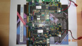
Interesting, then maybe you can clue me into something. In the picture I have two SGCC chips. I thought the lower numbers were dates much the same as others have told me in discussions. The underside of these chips are quite different. I have seen a chip from others that show the date only out by a day 8847 vs. 8846 but on a similar but altered PCBA.
The lower PCBA is from a MiniScribe 8425. Do you have a 8425 with the same PCBA 08AB with the same Model number BXX??? What does the SGCC number does it use? The upper one is from a 8450 if you were wondering.
shows PCBA 8425 and 8450.JPG
 
8847 and 8846 are a week apart, not one day. That would correspond to 46th and 47th week of 1988.

My 8438 has a QFP rather than a DIP package. My 8425 does match yours, however. 8425A and 8425S do not have this part at all by the looks.

What makes you suspicious of this component? I've seen nothing in this thread that suggests anything related to the drive itself being bad.
The upper PCBA is from the 8425 which will go through it's self check with JP13 and self park. This was given to me 25 years ago and was labeled as "please PD" as I must assume as please destroy or deposit. 25 years ago the drive would only flash and did not spin. Recently I wanted to restore the PC it came in, an 1988 Amstrad 1512SD. The 5 1/4 Tandon floppy was bad as well so never did boot. Replaced the Tandon with the same model and now it boots with floppies. The HD in question I got to spin but still would not read the disk. Tried SSTOR and the Amstrad maintenence disk but nothing got it to read the disk. I decided to open it up and I could see the heads must have fused to the disks as I could see where they seemed to have a dark spot on them which I assume was heat. The damaged heads must have been scratching the disks as they do not shine like gold mirrors but more like scuffed gold.
In other words, the PCBA on the top is fully functional. The lower one I got online eBay but came totally dead. I could have returned it but wanted to correct it's problem. I resoldered SGCC 4460100 DIP22 and it got the disk to spin but that was all with the general flashing error. I did notice the monitor gave the error something like " Drive Controller not communicating". I wish I stopped there and thought some more about what to do next. I could only assume resoldering the DIP22 got some power through it. I should have tested every pin to see what frequency I had coming through it but no, I had to try to swap the chip with the one from the 8425. I replaced the chips with sockets to easily swap and test but I accidentally broke the 8450 one. 🤦‍♂️I am new to removing these things. At least now I know how careful I need to be to do this. To be honest I think the 8450 was in a hot environment as all solders were sorta black and board dull and not shineable like the 8425. I think the chip was overly brittle. I have cleaned it up in the picture. Well now I also know these chips must be made specifically per PCBA as the swap using the original 8450 PCBA gives me a spinning drive but no stepper motor action. If I put the complete 8425 PCBA onto the 8250 drive it spins the drive plus the stepper motor will seek track zero but then just goes into the general error. I know, the BIOS for the drive (the DIP40) is not set for doing this but it was interesting to see what would happen. No fdisk or DEBUG will find the drive in any case. I'm sure someone is cringing while reading this but I am improving skills.
Good news is I have sourced an exact copy MiniScribe 8450 with a guarantee it works. I look forward to get that working on the Amstrad and then meditate on where to go or what to do to repair the 8450 I have now. Ohmmm... (carefully meditating)
 
I need to ask, is the basic Miniscribe 8450 an MFM or an RLL drive? From what I read it might do both but with MFM it will have 33% less disk size.
I wish to use the DTC-5150CR that says it only reads MFM. Others say it can be ST412 or ST506. I am going by Stanson that others have said isn't always the best source.
 
MFM and RLL are functionally "The same." They only difference between them is the analog encoding method passed to the disk. The entire rest of the system is exactly identical, and no drive can actually tell whether it's operating at 5MHz (MFM) or 7.5MHz (RLL)
With RLL, you trade some potential loss of reliability for 50% more sectors, which increases the aerial density resulting in faster transfer speeds, and of course 50% extra storage. A 10MB drive "becomes" 15MB and so on.
I have never met a drive which would not work with RLL, but back in the day many vendors produced "special versions" of existing drives that were RLL certified.
An 8425 and an 8438 are exactly identical under the hood, only the 8438 is "certified" for RLL. Same for the Seagate ST-225 and ST-238R, or the ST-251 and ST-277R.
Keep in mind, however, that RLL is really just storing more bits per transition on the surface, so an error in one transition can affect more than one bit. Because of the very limited (and in some cases nonexistent) ECC on many controllers, this adds up fast into unrecoverable tracks. This also means that any factory defects (and new ones since the drive was made) get bigger and span more sectors, potentially turning an otherwise okay enough track into one that should never be used. Many "RLL certified" drives of the day had very few bad sectors as the standards for the media were much, much higher on purpose.
All this said, you can run the drive as "MFM" and it will not notice a difference, and in practice buying an "RLL certified" drive and running it at MFM data rates was an excellent way to have a more-reliable-than-average drive.

The difference between ST-506 and ST-412 is minor, but somewhat important. The ST-412 interface is a minor update, which swaps the "Reduce Write Current" signal with another head select line (bumping from 8 to 16 heads addressable per-drive) and allowing "Buffered seek," or profiled seek. This is to say that the controller can send a series of pulses to tell the drive to move 10, 20, 100 tracks at a time and the drive will count these pulses and calculate how fastest to move that distance. These pulses can generally be sent at "any" rate faster than 3 milliseconds, down to something crazy like 30 microseconds on many drives. An ST-506 drive does not support buffered seek and so the controller must signal the drive to move individually one track at a time. The buffering and profiling fall on the controller, and the standard rate was 3 milliseconds, hence the cutoff. Any faster than this and most "real" ST-506 type drives will start dropping seeks left and right and you wind up in the wrong section of the disk, possibly corrupting data. In my opinion, the lack of buffered seeking is the most major difference between ST-506 and ST-412, as an ST-506 drive will NOT work with an ST-412 controller as a result of this. The utility of write current reduction is highly debated, this is here to assist with data integrity and bit crowding around the inner tracks, which is not such a big deal if you don't really care about what data is being stored, as I imagine most people with tiny vintage hard drives don't.
An ST-412 drive can be connected to either controller. The only change is that the ST-412 drive will be just as slow as any other ST-506 drive +/- some. You only need set the RWC value outside the range of cylinders for safe operation.
An ST-506 drive CANNOT be connected to an ST-412 controller without modification.

Long story short, your 8450 (and all 3.5" mechanisms I've ever seen or heard of) is ST-412 compatible. On top of this, because it is RLL certified, you can literally attach it to any controller ever made (excluding ESDI which has the same physical connectors but is NOT electrically compatible) and it will "just work" just as reliably as it left the factory, in theory.

What do you mean by "Scuffed gold?" I've never seen 8000 series with *gold* platters. I'd heard Miniscribe offered ferrous media on them still, but I'd be astounded if it appeared gold. The older ferrous media appears orange or brown. Almost all 8000 series, and certainly anything RLL certified in that range like the 8438 and 8450, should be using metallic media, which is a silver or gray color. A scuffed look is normal to some degree, they are shiny and reflective, but they are not a mirror finish. This is caused by the spreading of solid surface lubricant along the surface of the platter, which diffuses light somewhat and gives a blurry look across the disk. Any scratches or gouging typically appear as deep rings of a lighter color, due to the speed at which they occur.

"Drive controller not communicating" is an INSANELY vague message and probably just replaces the standard IBM 1701 error code, which is a catch all for basically every error that any part could ever throw. What do you mean by "General error?" The firmware between an 8425 and 8450 will be different, but all Miniscribes seem to do the same seektest. That is, they test their sensor then seek all the way inwards and fast jump back to track 0. The "inwards" is defined by (in many cases) hammering against the physical end stop. Because an 8450 has more tracks than an 8425, this "hammering against the end stop" happens later than expected, and you might even get extra pulses of the sensor before it happens. Not to mention, that a jump to track 0 from there takes more steps than on an 8425. This means (to the controller) that there is either a physical discrepancy in the drive (too many tracks) which is impossible, or that the positioning system is dropping steps, which is why the drive throws an error and stops.

With any drive with any intelligence, like all Miniscribes have and most drives after 1982 have as well, any error deemed severe enough will cause the drive to appear as if it literally does not exist to the host controller. That is to say, they outright do not respond to any control signals. Some might respond with SELECTED WRITE_FAULT but probably not much else.

Was the 8450 original to this machine, or was it originally an 8425? If you put the 8450 in that machine with no changes anywhere else, it will still appear as exactly 20MB, just like the original 8425.
 
My Miniscribe 8438 failed again and it's been sitting on a shelf for quite a while now. I had some leftover TLE4905 hall sensors from the Alphatronic keyboard repair project and thought I could try to see if it fixes this issue for good.

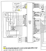
As per the 3650 schematic, it's possible to have an external index sensor:
1707490949364.png

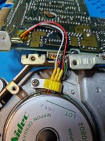
The same J7 is also present on the 8438 with the same pinout. I disconnected the grey wire going to the magnet sensor output and attached the TLE4905 to J7.

It appears to work fine, my biggest problem now is glueing the sensor at the right height and angle so it won't move and touch the motor or be out of reach of the magnet when i shove the PCB back in.

tle4905-j7.jpg
 
Back
Top