• Please review our updated Terms and Rules here

MiniScribe 8438 flashing error code

powerlot

Experienced Member
Joined
Nov 20, 2021
Messages
482
Location
Europe
Hi all

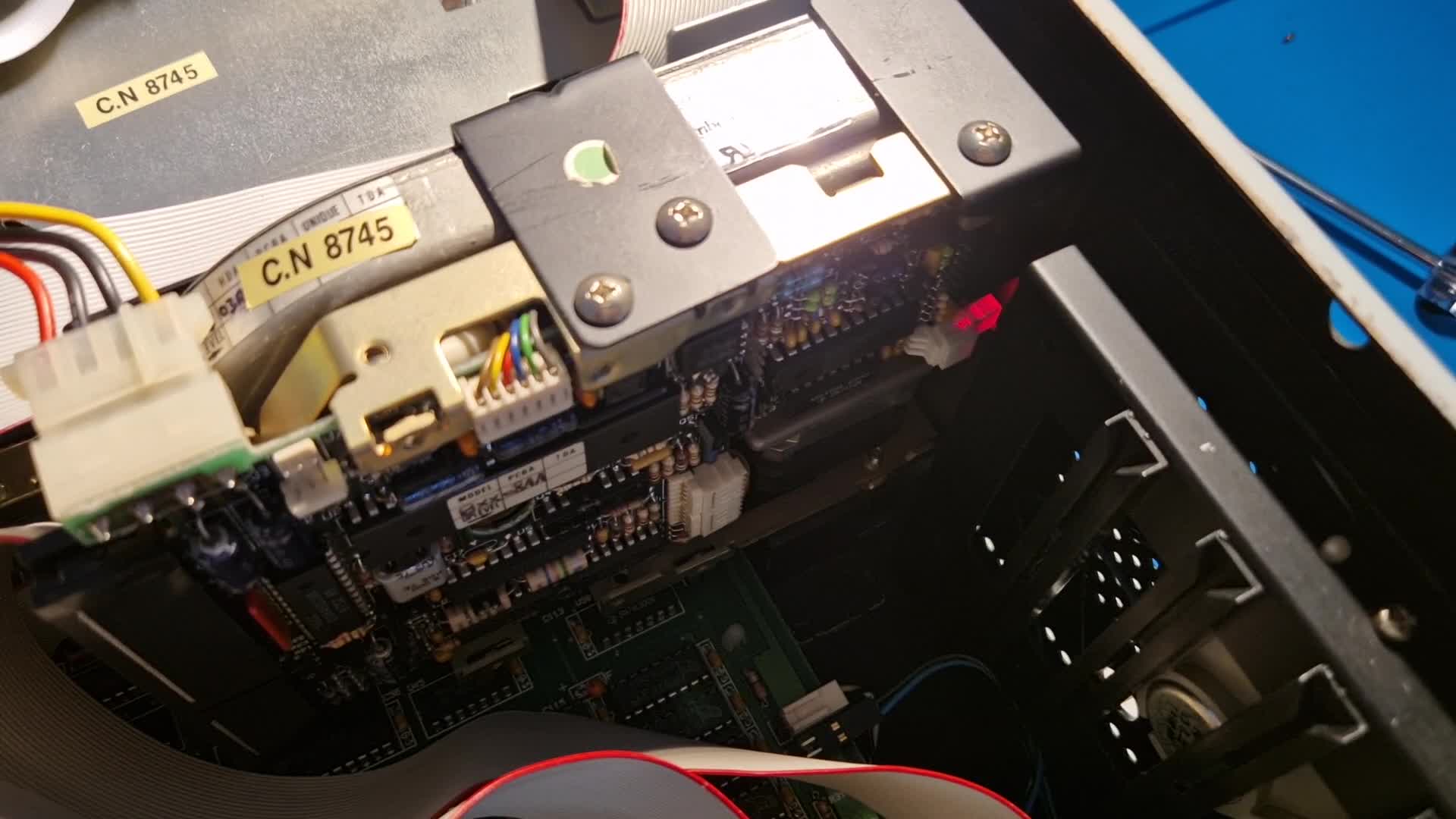
I have an XT clone with a Transteque HC-101 A1 controller card and a MiniScribe 8438 hard disk. It was working fine a few weeks ago but now it spins up and a moment later down again, then flashes an error code:


According to this it's "Code 4 - Index pulse not detected during spinup", if I got this right?

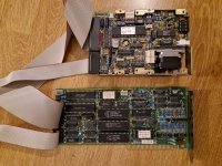
Where do I start? I reseated the ICs on the controller and tried different slots, but the problem is probably the drive itself, right? I also didn't find any documentation about the controller card... I hope it'll be fine.

Thanks for any hints!
 

Attachments

  • miniscribe8438-transteque-hc101.jpg
    miniscribe8438-transteque-hc101.jpg
    400.8 KB · Views: 18
According to this it's "Code 4 - Index pulse not detected during spinup", if I got this right?
I agree with that.

... but the problem is probably the drive itself, right?
I expect that the error code will still be present when the drive is powered on when the data and control cables are disconnected from the drive's rear.

'Index pulse not detected' is a drive problem. There is an index sensor and associated circuitry in the drive. That combination produces an 'index pulse' per revolution of the spindle/platters. During the drive's self-test, the self-test expects to see index pulses shortly after power-on (i.e. informing the self-test that the spindle/platters are at least rotating).

So, either the spindle/platters are not rotating, or there is a faulty index sensor, or faulty index sensor circuitry.

When I watch and listen to your video, I hear the spindle/platters starting to rotate ('spinup'). So, a faulty index sensor, or faulty index sensor circuitry, is suggested. However, I think that the first thing to try, is to re-seat the connectors scattered about the drive. One of those connectors may be associated with the index sensor.
 
Hi modem7, thanks for having a look.

I disconnected and removed the PCB now to check underneath, but apart from some minor dust which I cleaned off there was nothing obviously wrong.

The connectors aren't corroded at all. After reassembly the behaviour is the same (and as you mentioned it still does this without the controller attached).

I couldn't find schematics for this particular drive, but I did find this thread on eevblog: https://www.eevblog.com/forum/repai...mb-hard-disk-repair-index-pulse-not-detected/

Would also see this as the next step? Try to find out if the sensor is working?
 
Ok, I tried doing what's described in the eevblog thread. It looks like the sensor is working... I have no idea if the voltage level is what it's supposed to be but there is _something_


Tomorrow I'll try to check the other components connected to the sensor
 
It goes to pin 3 of U1, SGCC 004460100. An IC for which I can't find a datasheet for. That's pretty frustrating...
 
Connect a probe to pin thee, and see if the pulse is still there. If it isn't, then you'll have to trace back to see what it is going through / connected to and check there...

If it is pulsing... Well. I did see a Chinese site selling "100% guarantee components quality: Genuine Original."... And they say datasheets available upon request... Good luck with that.
 
It is directly connected to pin 3, there are no other components in between. I also noticed that the signal is permanently +5V and gets pulled down to about 2V on each reading.

I asked one of those chinese sellers for a datasheet to give it a try. If this doesn't work out and there is no schematic this drive will end up in my junk box in the basement :/
 
A question is, is the "about 2V " low enough?" Data, if it can be found, on the the 'SGCC 004460100' chip should answer that. Scope the chip's other pins; maybe you will see the index signal exiting the chip.

I have a Seagate ST-412 in which, many years ago, developed a fault. I could see index pulses going into a Schmitt trigger chip, and no pulses out of the Schmitt trigger. The problem was that the index sensor was not pulling down the signal enough. I added some electronics to compensate. A photo of the modification is at [here].

( Someone later posted an eBay source for the sensor. )
 
Update on this topic, as my XT is in pieces anyway. I haven't found a datasheet whatsoever, but I obtained another Miniscribe drive for cheap as donor, as the parts look more or less the same across Miniscribe drives.

Since it spun up correctly, I checked the index pulse on the same IC pin 3 of U1 and while the pulses were positive going, they were clearly going from 0V to 5V and not some half state in between.

Can I assume that the sensor in the Miniscribe 8438 has become faulty and cannot pull the signal low enough to register as a pulse?

I wanted to swap it, but the Miniscribe it is assembled in a way that would require pulling the spindle assembly apart and sacrificing the drive completely.

The donor drive had a missing JP2 which caused it to overheat around the stepper motor control circuitry... I have fixed it, unstuck the drive and lubricated the stepper motor. Now it flashes 1010 "Code A - Track Zero interrupter misadjusted" ...and it does look out of place.

What would you recommend? Try to fix both drives? Forsake the donor drive and steal its sensor? No idea how to adjust track 0... @modem7, how exactly have you modified your sensor?
 
I wonder if you could 'help' the index sensor with maybe a 1k resistor between where your measuring it and 0v ?
 
Hmm where could I pull it down? If I do that where I'm measuring it just pulls the +5V down, but the dip in the signal stays at the same level.

I'm going try to compare both circuits while they're running, maybe I can find out why on one design it goes from positive to negative and vice versa on the other.
 
Can I assume that the sensor in the Miniscribe 8438 has become faulty and cannot pull the signal low enough to register as a pulse?
No.

@modem7, how exactly have you modified your sensor?
By adding circuitry between the transducer (sensor, pickup, ...) and the circuitry that receives the transducer's signal.

We've been using the term 'pull down', but because the transducer is an 'active' device (i.e. fed +5V), it is more likely that the transducer is 'driving' the signal low.

I must point out that my particular solution was specific to my particular situation (combination of my drive's electronics and the nature/amount of the failure) - it is not a generic solution.
The 'correction' circuitry that I used for my particular situation is shown at [here].
Four diodes and a resistor. The diodes are standard 'small signal' ones.
The aim was to get the bottom of the pulse falling below the lower threshold voltage of the receiving chip.
It didn't matter that the high part of the signal also dropped - it just needed to be comfortably above the upper threshold voltage of the receiving chip.
Because I had a data sheet for the receiving chip, I knew what those thresholds were (and I knew the output pin of the chip).
For the count of diodes, and the value of the resistor, I had to experiment.

A photo of the circuitry is at [here].
 
The donor drive had a missing JP2 which caused it to overheat around the stepper motor control circuitry... I have fixed it, unstuck the drive and lubricated the stepper motor. Now it flashes 1010 "Code A - Track Zero interrupter misadjusted" ...and it does look out of place.
A related thread is at [here]. That's for a different model of Miniscribe drive, but things will be quite similar. Flag/arm loose on shaft?
 
Thanks for posting the circuitry. While I was experimenting with diodes and resistors and had them shoved in the connector, I noticed that the fault is intermittent and somewhere between the connector and the sensor/motor circuitry.

When I wiggle it or press my thumb down on the connector the signal gets below the threshold and the drive spins up. The usual clean up didn't help, so I have to check where the issue is exactly.

A related thread is at [here]. That's for a different model of Miniscribe drive, but things will be quite similar. Flag/arm loose on shaft?
When I manually rotate the interrupter until the arm is halfway in and spin up the drive, it travels back until it hits some end position, then flashes the error code
 
Now it flashes 1010 "Code A - Track Zero interrupter misadjusted" ...and it does look out of place.
A related thread is at [here]. That's for a different model of Miniscribe drive, but things will be quite similar. Flag/arm loose on shaft?
When I manually rotate the interrupter until the arm is halfway in and spin up the drive, it travels back until it hits some end position, then flashes the error code
DONOR DRIVE:

When the drive's self test executes, if the self test does not see the track 0 sensor initially activated, the logic will be something like: The heads are most likely off track 0. I will step the heads out until I see the track 0 sensor activate. If after {drive's count of tracks} steps, the track 0 sensor still hasn't activated, then I will declare a failure.

Your "hits some end position" could be the heads reaching track 0, and if so, if at that time the arm is not within (or not adequately within) the track 0 sensor, there's your problem.
 
Regarding the MiniScribe 8438:

I've taken the molex pins out of the connector, brushed them with a fiberglass pen and tried to re-tighten them. It looks like it's working again, the index pulse signal is 'driven low' to about 0.5V now.

Thanks for your help. In the end you were right and it wasn't the sensor. One should probably also not assume that reseating connectors and spraying cleaner will solve all contact issues.


Regarding the MiniScribe 3650 - now that I have it I might as well try to fix it and keep it as spare.
Your "hits some end position" could be the heads reaching track 0, and if so, if at that time the arm is not within (or not adequately within) the track 0 sensor, there's your problem.
How do I know it read a track 0 vs. it hasn't found one? It does stop when the arm passes the sensor. If I further rotate it inwards, the heads stop in the middle of the platter with the same error when passing the sensor.

The controller posts a 1701 (drive not ready) - should I attempt a low level format?

"Error Reading Track 0"

A. Hard disk not formatted.

Here is a video of normal operation:


Here's what mine does:


I'll check for dodgy connections this time :)
 
One should probably also not assume that reseating connectors and spraying cleaner will solve all contact issues.
Definitely not.

I had an intermittent card that had been affected by NiCad battery leakage. 'Chemical cleaning + pencil eraser' made the edge connectors appear to be good, but it wasn't until I used something with decent abrasiveness that the problems disappeared. Coincidence?

I have two Toshiba T1100 laptops. On both machines, the connector providing power to the 3.5" drive is problematic. After cleaning, re-springing contacts, etc., I still cannot get the connection reliable. I have sometimes thought about soldering the wires to the drive, but because this has to be due to some form of deterioration in the connectors (it won't have left the factory like that), I should investigate replacement connectors first.

The controller posts a 1701 (drive not ready) - should I attempt a low level format?
No point.

1. The drive, having failed its self-test, will be reporting to the controller card as not 'ready' (i.e. not ready for operations of any kind).

2. Although the drive contains a microprocessor and can do a limited self-test, the intelligence does not extend to the ability of the microprocessor to interpret what is recorded on the platters - that is the job of the MFM controller card. In respect of head positioning, the drive simply responds to commands from the controller to either step the heads in or step the heads out. Example at [here]. The drive uses the track 0 sensor for:
- It's self-test; and
- When the heads are on track 0, to signal to the controller that the heads are on track 0 (see the 'TRACK 0' part of the interface diagram at [here]).

Here's what mine does:
When the heads are on track 0, the flag appears to be within the track 0 sensor. But to prove operation of the track 0 circuitry, one would need to work out what the track 0 circuitry is and then do measurements.

However, what I am not seeing is the heads stepping in. Another connector issue? One of the two chips used to drive the stepper is faulty?
 
Definitely not.

I had an intermittent card that had been affected by NiCad battery leakage. 'Chemical cleaning + pencil eraser' made the edge connectors appear to be good, but it wasn't until I used something with decent abrasiveness that the problems disappeared. Coincidence?

I have two Toshiba T1100 laptops. On both machines, the connector providing power to the 3.5" drive is problematic. After cleaning, re-springing contacts, etc., I still cannot get the connection reliable. I have sometimes thought about soldering the wires to the drive, but because this has to be due to some form of deterioration in the connectors (it won't have left the factory like that), I should investigate replacement connectors first.
Good to know and something to look out for in future troubleshootings. I was about to directly solder the wires as well and I'm probably going to if the connector starts to become problematic again. I'm also hoping that the wires don't break or corrode internally.

However, what I am not seeing is the heads stepping in. Another connector issue? One of the two chips used to drive the stepper is faulty?
Yes, I noticed that as well and wasn't sure if that's the self-test deciding to abort any further movements or the next fault to look into.

I understand that JP1 and JP2 set some factory configuration and one of the settings could be some sort of exercise / burn-in test? I didn't find any specific descriptions, but if one of the tests would move the heads back and forth I could measure the signals in the stepper motor circuitry. The area around U6 and U7 did get really hot within seconds with JP2 off so a fault in one of the chips or surrounding components could be possible.

The schematics of other Miniscribe drives are very similar to the 3650 and even the PCB numer is the same (300353100 P1): https://archive.org/details/bitsavers_miniscribe085Schematic1987_2072293/page/n7/mode/2up

I'll try checking for broken / burnt components and if none look wrong, use my scope to check if there are signals telling the drive to step in according to the theory in the pages you linked and the schematics above.

Will be back in a week or two with results...
 
I don't know if it would help at all, but I have a number of PCBs and even disk assemblies from the Miniscribe 8425/8438 twins that are faulty and malfunctioning. Would be glad to give them to a good home. ;)

Track 0 on most Miniscribes is adjustable by rotating the interrupter on the stepper motor shaft (I acquired a 8425 about 10 years ago that had a totally worn out track 0, could not format. Adjusted it so track 0 is closer to the outside of the platters, and the drive is happily chirping away to this day, with a batch of bad sectors where the old track 0 was). If adjusted too far in either direction though, it will have problems finding the sensor. In that case you will get a 1701 error from the system. Could it be that your donor drive has a misplaced interrupter?
 
Back
Top