• Please review our updated Terms and Rules here

Model 30-286 motherboard in a Model 25 case?

raifield

Experienced Member
Joined
Aug 3, 2010
Messages
174
Location
NJ, USA
I came across an auction for a Model 30-286, it seems the same as a diagram I found for the Model 25-286 board and I was toying with the idea of swapping out my Model 25 8086 board for it. In the interest of cost, I assume IBM manufactured only one type of Model 25/30-286 board and simply dumped them into whichever case they wanted, meaning that the ISA riser would line up in my case. My Model 25 is the MCGA version, so I am making another assumption that VGA would have no issues syncing with the monitor. The computer I'm typing this on still supports 720k drives in BIOS, so I'm sure an AT-class system won't have issues with them.

Am I on the right track here? My whole idea falls apart if the motherboards for Model 25-286 systems and Model 30-386 systems are different.
 
I can't remember much of my research from the early 90s on my 30-286, but if the case if the same size, I bet you could swap them without a problem.

I can't remember which model came with the 8088 and dual 720ks, but I have one of those too and inside it was about the same size, with the case being almost identical to my 30-286.

With the video being built-in like modern PCs, you'd get a nice video upgrade with the motherboard upgrade as well as a bit of a cpu boost as I think the 30-286 had a faster clock speed.

What was interesting about the 30-286 3.5" drives was that they purposely left off the second sensor in the drive to detect 1.44mb and 720k. So you could actually format 720ks to 1.44mb all day long without a hole punch tool. And with some utilities and a small tsr, you could actually get 1.86mb out of them.
 
I know they are VERY similar planars on ALL model 25 and 30 units, but I KNOW there are differences in the riser card, so it might take some creativity to get them to fit. But the cases are VERY, VERY close, you have a good shot at making it work, riser card should be the only hurdle to overcome.

I also know the built in screen will do VGA beautifully, some members here (evildragon comes to mind) have modded an ISA VGA card into a Model 25 and hooked it into the built in display, so you should have no issues with a VGA upgrade. I never went with this mod, I am just fine with MCGA on my Model 25, adequate for my needs, and I would rather have my slots filled with SCSI card and Ethernet card.

EDIT: I know there were some planar upgrades that could take you all the way to a 486 (or even a 5x86 if you upgraded the 486 CPU). A company called REPLY made an aftermarket planar that fit the Model 25 and 30, not sure how easy one of them would be to find, but I know they exist, large CPU, Video, and RAM boosts with those upgrades.
 
Last edited:
What was interesting about the 30-286 3.5" drives was that they purposely left off the second sensor in the drive to detect 1.44mb and 720k. So you could actually format 720ks to 1.44mb all day long without a hole punch tool. And with some utilities and a small tsr, you could actually get 1.86mb out of them.

I would not recommend using disks at the wrong density for very long, and not for important data storage, they tend to not be stable, Much, much different magnetic density on the disk surface.

Now the 1.68 and 1.86 (and a few others) disk formats on HD disks are just fine, technically a HD floppy is 2MB unformatted, the 1.68 and 1.86 formats are just using different formatting schemes to squeeze more data on the disk with less file system overhead. Winimage will let you pull this off with a few formats, create a new image add some files to it, and then write it out to a HD disk.
 
Thanks for the replies. I ordered the board, so we'll see how it goes. Looking forward to playing my KOEI EGA games in color instead of CGA's black and white. I'm hoping the board will power a Disk On Module unit without an external power supply, but we'll see.
 
I finally found a 3.5" 720K disk that I had punched to work as 1.44M in my recycling pile. It was good when I first punched and wrote to it--it won't format now at all.

Take this as a caution.
 
Thanks for the replies. I ordered the board, so we'll see how it goes. Looking forward to playing my KOEI EGA games in color instead of CGA's black and white. I'm hoping the board will power a Disk On Module unit without an external power supply, but we'll see.

Does your Model 25 have a color CRT? Swapping boards wont give you color if you only have a black and white CRT. That said, there were color model 25's and I am not sure what one you have. The built in MCGA is capable of 256 color in "mode 13" and up to 16 colors in straight CGA mode, so if you have a color CRT you should be able to get color now, if you have a black and white CRT you would get multiple shades of gray instead of color.

My Model 25 powers an old 3.5" SCSI hard drive tapped off its PSU, if it can do that, it should have NO problem powering a DOM or CF card.
 
I have the color version, the KOEI games are black and white because the good folks at KOEI programmed their early EGA games to fall back on CGA's 640x200 2-color mode if an EGA-compatible adapter wasn't detected. The graphics are actually quite functional, but color still makes a big difference.

I have no confidence in my ability to modify the PSU without destroying something, I'm hoping the onboard IDE interface supplies power on pin 20. Otherwise I'll have to go with an external SCSI drive.
 
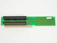
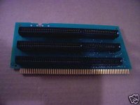
I have met with both success and failure. The Model 30-286 board arrived today and is form-exact to the Model 25 board. Unfortunately, the riser card is not. The Model 30-286 apparently has three ISA slots, but the Model 25 case only has vertical space for a dual-slot riser. The board works perfectly fine, but now I have no ISA slots.

I don't want to try putting the original Model 25 riser card in, I'm concerned that the difference might short something and destroy the board. Now I need to find the part number for the 25-286 riser and track one down...hopefully. I'm also toying with hacksaw-ing the Model 30-286 riser card, but god knows what that will really result in, plus I would hate to destroy equipment like that.

Edit: The part number for the riser is 64F0182. I've found a few sites advertising an inventory of them, so here's hoping.
 
Last edited:
Yeah, I knew riser mods would be required for this one....

More than likely if the traces all look straight and not looping back around, and you cut it cleanly, you should have no problems using a cutoff riser in it. Even if there are some traces that loop up and down out of the area that needs to be cut off, it would likely be possible to bridge it with wire. You will need to be precise on cutting too, if you just hack at it with the wrong tools you might end up lifting traces that you need, you will want to be sure to make a nice CLEAN cut.
 
I'd suggest a dremel tool on the back side where you can cut things cleanly. As RWallmow says, double and triple check the traces on that upper half, and bridge whatever loops back downward.

This'll be a cool project if you pull it off - don't forget the pics!
 
I'd suggest a dremel tool on the back side where you can cut things cleanly. As RWallmow says, double and triple check the traces on that upper half, and bridge whatever loops back downward.

This'll be a cool project if you pull it off - don't forget the pics!

I thought dremel at first too, but wondered if it might tear at the traces since it spins and could catch and have chances of lifting them. Maybe a sheet metal shear or nibbler I would think would be cleanest cuts, but those are tools that aren't exactly part of a DIYers "tool belt".

I dunno, a dremel might work, but maybe practice on a scrap circuit board (PCI winmodem or some other plentiful and useless board) first to be sure its not going to lift traces.
 
Maybe you can try the masking tape trick: cover the section to be cuted with masking tape so the dremel won't be able to lift traces.

I haven't used this method with electronics, but for cutting wood without lifting paint or wood finish it works very well.

Jose.
 
I think masking tape would be too weak to hold anything down and the space between the ISA slots are too small for tape anyway. I'm thinking a small hand saw with a very fine blade might be better.
 
I thought dremel at first too, but wondered if it might tear at the traces since it spins and could catch and have chances of lifting them. Maybe a sheet metal shear or nibbler I would think would be cleanest cuts, but those are tools that aren't exactly part of a DIYers "tool belt".

I dunno, a dremel might work, but maybe practice on a scrap circuit board (PCI winmodem or some other plentiful and useless board) first to be sure its not going to lift traces.

My Dremel is an old one for sure but spins at about 10,000 RPM, so it's not going to stub it's toe along the way. :sly:
 
Well, while I wait for my friend to find his Dremel attachment, I did try plugging in the ISA riser from the 8086 Model 25 board. With the riser installed, the system refused to power on. Removing the adapter put everything back to okay.

I'm going to try to plug the Model 30 riser into the board and tilt the assembly so I can see the screen without having to close the case. This isn't my brightest of ideas, but why not? Still trying to track down the genuine riser for the Model 25-286.
 
So in the end, I did find and purchase a Model 25-286 riser, which works fine. Here is a summary of my ultimately fruitless conversion attempt:

The Model 25-286 and Model 30-286 motherboards are the same board.
The Model 25 8-bit ISA riser will not work in the 286 board, the system will not power on.
The Model 30-286 riser has one more slot and crucially, places the lowest slot about half an inch higher than the lowest slot on the Model 25 chassis, making usage of the Model 30-286 riser impossible, modified or not.

Ambry.com is selling the 25-286 riser under IBM FRU 64F0182 for $30 and mine arrived quickly and well-packaged. I installed my ATI Stereo F/X card and am now enjoying some old-school CMS tunes.
 
Back
Top