• Please review our updated Terms and Rules here

Model 4D Gate Array - Screen characters missing first bit

dmemphis

Experienced Member
Joined
Oct 4, 2014
Messages
262
Location
Pottstown, PA
I started this one last year but can't find the thread. I'm back on it now
tired of having this nice machine sitting here in two pieces in a bad way.

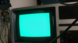
This is the symptom - the first pixel of every character clocked out to video is dark.
http://imgur.com/PIhmEPy
Its dead consistent from power up to power up.
D's and Y's look normal I think because they are narrow and centered- their first dot is blank anyway.

I swapped the character ROM and the display controller ICs - no change at all.
I checked that the data path between character ROM U19 to PLD U17- its good; there
are pulses on D0 at both ends (How I hoped this signal was the problem I expected a bad
ROM driver or open trace but NO!) (I scoped ON the pin at the PLD, so I know the ROM bits get there)

I looked at all the signals around U17, U19, U16, U12, U14,U15- they look healthy.
I'd like to swap in replacements for U17, U9, and U8 but this is the only Gate Array board
I have.

Know of any failure modes that might obscure the first dot of every character clock out?

I mostly suspect a weird failure in U17 as it does the shift of the ROM byte and could be doing
something wrong with the first bit. I'd need a spare U17 to check that with.
Or it could be the PLA is being told to do something wrong, ie: its erroneously
putting out a non existent graphics bit at that time instead of the ROM bit. I don't
fully understand the switching and mixing of the graphics data with the character data.

I'd hate to think its a really hairy timing thing that I'll have to measure all the signals in detail...

Thanks in advance TRS-80 commandos.
 
dmemphis,
It's hard for me to understand what you are trying to describe. You say the first pixel of every character is dark.
But, your LDOS screen doesn't really show me anything that appears that way. If I were a LDOS user maybe
I would understand more.

The Characters are laid out in a 8 x 9 (Row - Column) Grid. I've selected 8 as examples (A, B, C, D, a, b, c, d)
They are shown here from the CG-7 Character set (Source: MCM6674 Data Sheet. This is the older CG with
Katakana alternate characters Letters shifted 1 line down to match M4 style)

AB.jpg CD.jpg ab.jpg cd.jpg

Can you post a picture with a line on the screen that has: A's, then B's, then C's, then D's, then a's, then b's, then c's, then d's?

That would mean more to me.

Are you saying that each Character has a Dark Pixel like these"

DAB.jpg


In the meantime I'll look at the Model 4 Circuit.

Larry
 
Last edited:
Did you check the two video ram chips? Couldn't one of them stick a bit if bad?

If it ends up being one of the support chips, I'm sure one of us has a spare we can find, myself included, if they are the same chips between 4P and 4D.
 
Hi thanks gents for chiming in.
I'm sorry that my screen shot didn't really illustrate the symptom as clearly as I thought it would.
I can get you a shot of various letters to make it clearer what is missing; yes you have to
know what that screen is supposed to say in order to see what is particularly wrong.
BUT
In the meantime, I can describe it in terms of the character cells you presented.
In fact my title and description needs clarification:
Each character on the screen is missing its first column of dots that are supposed to be on- which
would be column 2 of the character cells. So capital A is missing the dots of column 2, the left most
set of dots that form the A.

The video ram only holds ASCII values, I THINK that the RAM is good because it is attempting to
display the right ROM cell. Unless the ASCII character is pulled for every dot, and reloaded each time
and something is causing the wrong ASCII char to be pulled at the beginning of each clock out.

Thanks!
 
Did you point to the right screen shot? In the one posted it is clear that the 8th bit of video RAM is stuck on. There are no ASCII characters on-screen there just graphics characters ($80 .. $BF) and the extended characters ($C0 .. $FF). Most obvious are the spaces which are displaying as graphics character $A0 instead of $20.
 
dmemphis,
Yes, that does make sense. The second Column is missing the information from the Character Rom which is Bit D1. The RA0, RA1, RA2,
and RA3 Address Lines are used to address the nine columns in each Character Block. Each Row contains 8 Bits of data from the Character
Generator. You have changed the Character Generator, and the CRT Controller, and neither of them fixed the problem. So, looking at the
Schematic it has to be something that contains the DATA from the Character Generator U19. That pretty well leaves a couple of possibilities.
U17 the Video Array or U13 the Adder 74LS283.


Try these programs to see if the Graphics are displayed properly along with the ASCII Characters that
are missing the Pixels from Column 2 (D1). This should tell you a bit more about what is going on.


If your system is stable enough to run some Basic programs you can try the following:

Basic Programs to display:
1. Special Characters
2. Text Characters
3. Graphic Characters


1. Special Characters
10 CLS
20 FOR I=0 TO 31
30 POKE, 15360+I*16,I
40 NEXT
50 PRINT@ 640,"";


2. Text Characters
10 CLS
20 FOR I=32 TO 127
30 PRINT@ (I-32)*8,I; CHR$(I);
40 NEXT
50 END


3. Graphic Characters
10 CLS
20 FOR I=128 TO 191
30 PRINT@ (I-128)*8,I; CHR$(I);
40 NEXT
50 END


5 CLS
10 POKE 16526,105
20 POKE 16527,0
30 X=USR(O)
40 PRINT CHR$(21);
50 INPUT "PRESS ENTER TO SEE SPECIAL CHARACTERS";X
60 FOR I=192 TO 255
70 PRINT CHR$(I);
80 NEXT
90 PRINT
100 INPUT "PRESS ENTER TO SWITCH TO ALTERNATE SET";X
110 PRINT CHR$(22);
120 INPUT "PRESS ENTER TO RETURN TO NORMAL AND END";X
130 PRINT CHR$(22); CHR$(21)
140 END


By running these Basic Programs you can get a picture of all available Characters in the Character Set and compare
them to what it really should have.


Larry
 
Gents a thousand pardons.

This is the danger of not uploading a photo and seeing a confirming thumbnail. Please see the second photo in the following album which is a green screen boot image of trsdos on the 4D. I hope my description is now clearer.
http://m.imgur.com/a/4xo07

That first photo was a model III problem from last year and yes it was a video ram problem correctly diagnosed in the posts above. Unfortunately is not the prob at hand...
 
Last edited:
Did you point to the right screen shot? In the one posted it is clear that the 8th bit of video RAM is stuck on. There are no ASCII characters on-screen there just graphics characters ($80 .. $BF) and the extended characters ($C0 .. $FF). Most obvious are the spaces which are displaying as graphics character $A0 instead of $20.

I did not! Its the wrong one.
2nd photo http://m.imgur.com/a/4xo07
 
Last edited:
dmemphis,
WHEW!!! A Dog that can blow Bubbles!!!!! I thought that was the next picture.

OH Well, I finally found the TRSDOS Image. Yes just as I was suspecting, the COLUMN of dots is missing from the Characters.
GP2000 brought up a good point that I overlooked, in that I assumed your picture really had missing dots versus being displayed
as Graphics. That pretty well points to one of the two IC's I previously mentioned.

There isn't a real good description of the Model 4 Gate Array, but the Model 4P has two pages along with the schematic that is a
bit earlier revision of the CRT Controller. I've extracted those three pages as PDF's, and if anyone wants them, or the Complete 4P
PDF I can email it. (They are too large to upload here.)

Thanks.

Larry
 
Last edited:
LDKraemer: Thanks for all the effort sorry for putting you on the wrong rail!
But the basic programs will be helpful. I might run them after I get this sorted out to make sure
my entire ROM looks good.

dmemphis,
WHEW!!! A Dog that can blow Bubbles!!!!! I thought that was the next picture.

Yes that would what one would expect on IMGUR!
I guess I'm an atypical IMGUR user, using it as just my own photo catalog?

dmemphis,
That pretty well points to one of the two IC's I previously mentioned.

There isn't a real good description of the Model 4 Gate Array, but the Model 4P has two pages along with the schematic that is a
bit earlier revision of the CRT Controller. I've extracted those three pages as PDF's, and if anyone wants them, or the Complete 4P
PDF I can email it. (They are too large to upload here.)

I have the small form factor Model 4/Model 4P Tech Manual, beige color binder.
Its not too bad on description, but not nearly as complete as the old Model I technical manual!
Thanks for offering to distribute the documentation- anyone interested in looking into it will need that.

I guess I'm interested in testimony of whether these gate arrays, especially U17, are getting to be
typical failure points... ie: are they starting to fail due to, say, poor fab and/or packaging.

If not, perhaps I should look closely at the things that drive U17 rather than expect to have to replace it.
 
demephis,
Since the missing dots won't hurt anything, you don't you put the machine through it's paces and see if it all appears to
function correctly. By the time you are done with that perhaps Ian will drop in on this posting and comment. He may
have already seen the same type thing.

I'd think it is just a glitch in the Video Array U17 or the Adder U13 (74LS283). You would likely see other problems
it it were a real hardware problem. It could even be a cold solder joint, or a thermal problem. Has the machine
worked previously, and just started doing this? Might be worth the effort to heat or cool the U17 a slight bit and see
if things change. I've seen IC's that you could just wave a heat source, over and they would quit working for a bit.

Good Luck.

Larry
 
Larry:

That is an excellent suggestion to put it through its paces and wait for some other eyes to see this post.
All I know at this point is that it boots off the drive :0

The machine is new to me. When I received it, it didn't work. The Power Supply was fixed-
bad connector and caps. The first I saw the screen, it looked like this.
FYI:
It does it from cold boot, and freeze spray around the video area doesn't change it.
I have not tried heat but that's a good idea too. I did reseat all the socketed ICs. I have not removed the board yet
so I have not seen the solder quality on the back.

DC
 
Bring up basic and fill the screen with CHR 191 (assuming in 80 col mode: For A=1 to 1920, print CHR$(191);: NEXT A. That way its clear if its the same pixels on all spots, that isolates it down to something stuck versus something random.

Remember, I do have a working video support chip from a GA 4P, and if it is the same and you get down to that being it, I'd be willing to pull it off my donor board.
 
Its solid blocks! No missing Columns!

Its solid blocks! No missing Columns!

Bring up basic and fill the screen with CHR 191 (assuming in 80 col mode: For A=1 to 1920, print CHR$(191);: NEXT A. That way its clear if its the same pixels on all spots, that isolates it down to something stuck versus something random.

Remember, I do have a working video support chip from a GA 4P, and if it is the same and you get down to that being it, I'd be willing to pull it off my donor board.

Well, this is interesting- its all solid. What's that tell you?

IMG_20170730_204402142.jpg

This might point the adders? (I think that's were graphic chars are handled different to ascii chars?)
 

Attachments

  • IMG_20170730_204402142.jpg
    IMG_20170730_204402142.jpg
    96.1 KB · Views: 1
It tells me that the Graphics section of the Video Array is 100% functional.
All the Graphics Characters should be 100% correct.

If you change the print statement to PRINT CHR$(65);
you will see the "A" printed minus the dots in Column Two (D1).

0x00
0x18
0x24
0x02
0x3E
0x02
0x02
0x02
0x00


Give that a try. In fact if you do that, and then had some way to capture the D{0..7} bits going to the
Video Array, you can probably see that the Dots are missing from Column 2.

Larry
 
Last edited:
Yes clearly its 100% functional. The questions is how can there be
a difference between the too- the answer lies outside the GA in how
grapshics are prescribed differently than letters? What is that difference...
Does this point back to the address adders?
I think it rules out something wrong related to how the (non existent) graphics boards
would interleave in.... unless graphics cards aren't allow to merge data with graphics
characters.

I did type a whole line of A's and they were missing the left side all the way across.
 
So printing the A's has shown a more complicated symptom!
The A's, printed in a row repetitively have their left edge intact - maybe except for one dot higher up in the A
which never seems to be there.
But as you can see on the last line of this capture, (I got suspicious) - with an intervening space char, the left
edge is lost!

dots1.jpg

So if there is an off time of a couple of dots, the next ON dot is not ON.
That's why the boot screen looks so bad- there are lots of spaces and most character sequences have
a few dot times off before the next characters dots are presented.
And this explains why the solid graphic blocks never lost a column- not because they were
the graphic character set, but because there were no off dots preceding a character.
I should probably try generating blocks separated by spaces and see- they should loose their
first column or two of dots.

Possible reasons?
- a logic driver rise time issue on the digital side where the ROM Video GA misses the bits
- or a beam turn on problem on the analog side.

There is another video problem showing up too... there is a pattern of extra dots appearing at the bottom
of the left leg of the A's, and it progresses slowly across the display. Here I have captured the
leading edge of the migrating extended legs near the center of the screen.

dots2.jpg
Seen migrating in action: https://youtu.be/K7-cAQWm8sQ

I'll be interested in what you guys think of this!
 
Last edited:
Have you verified the Character Genwrator with a replacement from another Model 4?
 
I'd start by replacing U16 (or just re-seating it) its the video memory chip for the characters and its a 6116.

It's most likely this or the U17 video gate array chip.

People often suspect the character generator (in all TRS-80s, not just Model 4s) but in my opinion I find they rarely fail, they are very robust. Try a substitute but its most likely working perfectly.

Just my 2c worth.
 
Back
Top