• Please review our updated Terms and Rules here

Monitor Philips CM11342

shad

Member
Joined
Apr 27, 2024
Messages
12
Hello,

Need help fixing my CM11342-05G having the following symptoms:

When turned on, the green light is on but the screen doesn't show anything and I can hear a squealing noise just for 1 sec and it is gone.
(not like when the flyback (LOPT) transformer is dead and it makes a continuous high pitch noise)

I checked all the rail voltages 128, 9, 5, 12, 28 and all are ok.
I checked R3563 and it is good reading 4.7 Ohm.

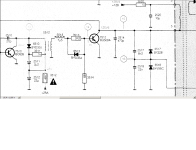
I noticed thought that the voltage across C2541 is zero while it should be -27V.
Also across R3534 it is zero while it should be -27V.

I have replaced the flyback transformer LOPT 5510 but the problem remains the same.

Which component(s) could be the culprit ?

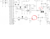
I have attached the schematics for this monitor. The 27V signal for testing can be seen in two locations on page 2.


Thanks,

Shad
 

Attachments

  • image.png
    image.png
    186.5 KB · Views: 5
  • CM11342.pdf
    4.7 MB · Views: 10
Excellent.

I see you checked all of the voltages except for +12A. Chan you check that as well please (just to make sure it is present and correct).

Dave
 
With the only two spots marked for the -27V there doesn't seem to be much chance of overload on that line (which would make me look at the components between C2541 and the flyback), but it may be more likely that there is no horizontal drive and the flyback is not operating. Do you have a scope to check drive coming from Pin 11 of IC7270 (TDA2579)?
 
Hello,

I did some checks today as follows:

- Components connected to PIN 10 of flyback transformer 5510 namely C2541, R3541, R3540, D6540 are all ok.
- Component connected to PIN 3 of flyback transformer 5510 namely R3520 is ok. and +128V is reading correctly.
- R3526 is ok

I don't have a scope, so I tested voltage at various pins of IC7270 using a voltmeter:
Pin 16 = 9.19V
Pin 15 = 4.49V
Pin 14 = 2.3V
Pin 11 = 0.75V
Pin 10 = 11.46V
Pin 8 = 2.87V
Pin 7 = 6.2V
Pin 6 = 6.39V
Pin 5 = 4.0V
Pin 4 = 7.68V

Seems its functional.


What else to check that could be causing the missing 27v signal ?
 
If the 27V is missing because the flyback is not operating or is not being driven, you should also be missing the G2 voltage (370V) that appears on pin 7 of the CRT.
Do you have any voltage there?
 
I would suggest the same measurement.

There is a lower voltage next to it that is also generated from the line output transformer that you could measure.

The problem with measuring voltages that are not DC or sine waves is that they don't actually tell you much - other than the fact that there is something there...

Dave
 
Hello,

That's correct, there is no voltage on Pin 7 (G2) of the CRT.

I measured voltage on other Pins of CRT as follows:

Pin 5 (G1) = 0.5V DC
Pin 6 (KG) = 121V DC
Pin 8 (KR) = 110V DC
Pin 9 (H) = 0V DC
Pin 10 (H) = 0V DC
Pin 11 (KB) = 118V DC

What's next to check ?
 
This is the area that can have the most problems related to loss of drive for the flyback. You can carefully re-check components and connections/traces in this area.
After that, you will be at a serious disadvantage without a scope.

drive.jpg
 
Hello,

I got some good updates and yes I have 128v at C2520.

Resistor R3512 was opened as it was reading 7 MOhm while it should be 4.7 Ohm. So I replaced it and made some successful voltage readings:

* At C2541 I got 27V
* On both sides of R3512 I got 28V
* At the junction of C2510 and D6510 I got 27V
* At PIN 7 (G2) of CRT I got 136V


But still nothing shows up on screen when i connect a device to RCA Video.

So I made some further checks, as per attached diagram, I noticed that:
- The voltage at the junction of C2514 and the collector of Transistor 7512 is 136V instead of 125.6V
- The voltgae at the junction of R3513 and the Base of Transistor 7512 is .7V instead of 1V.

I replaced Transistor 7512 and capacitor C2514 but still same voltage reading.

Any tips ?
 

Attachments

  • Diagran.png
    Diagran.png
    116.2 KB · Views: 3
Yes, stop replacing good components 😀!

A base-emitter voltage will read somewhere in the range 0.6 to 1.0 Volts - depending upon a number of factors.

If you are not using an oscilloscope, your voltage readings will be inaccurate (unless they are truly DC or sine waves - which they should not be at this point).

I am on a business trip until Thursday now. I will have a look at the schematic again when I get back to the hotel.

Dave
 
Transistor 7512 seems to be functioning because if it wasn't driving the flyback you still wouldn't have the -27V.
The G2 voltage is low, should be about 370V. Perhaps the G2 adjustment was fiddled with while it wasn't working.
Turn it up to see if anything shows on the screen, if nothing happens, return to original position for now during more troubleshooting.
If something does show up on the screen but still not normal, it may provide more clues for the next step.
 
Hello,

I appreciate your help DAVE while on your business trip !

Bburley, I have turned the G2 knob clockwise on the flyback transformer and I got a higher voltage on PIN 7 (G2) of the CRT.
I was able to reach 210V by turning about a quarter of a turn and I got a white background on the screen with horizontal lines.
Sometimes the screen shrinks to one horizontal bright line.

I connected a device to RCA Video connector but nothing shows on screen. Just the white background.
If I press the green button on the front panel, I get a green background.

Kindly note that the flyback transformer is brand new philips out of the box which i installed at the beginning of my repair.

Should I turn further the G2 knob to reach 370V or that's not a good idea?

Any tips ?


Thanks,

Shad
 
I would think it would be ok to leave it set just high enough to be able to see what is on the screen for now. I am not sure if it is stable or if it will change again if additional repairs are done.

It the raster collapses to a single horizontal line, that means that you are losing vertical sweep. Check carefully for bad connections in the yoke circuit and around the vertical output IC.

If you have no video displayed, that will be another problem to troubleshoot. Unless you get really lucky with voltage measurements and find something not right that leads you to the issue, the lack of a scope to visually see the signals is going to become more of an issue. Do you think you might invest in one of the digital scopes?

Here is an example although there are many to choose from. - https://www.amazon.com/FNIRSI-1013D-Plus-Oscilloscope-Bandwidth/dp/B0BHHYMVKV?th=1
 
I am going to state the obvious here (...), but you did select the button to CVBS when you connected a video signal to the RCA connector - didn't you?

Dave
 
GOOD NEWS !!!!! Monitor is working !

I was giving it another try by hooking up my Nintendo NES to the RCA Video Port and nothing showed on screen, but it happened by mistake that I pushed on the RCA connector downwards towards the board and BINGO ! I got a display ! If I don't apply pressure, the display goes off.
I noticed that the RCA had a bad connection on the board, literally the soldering was broken off. I fixed it by applying flux and all is good now.

The only problem I am left with is the display shrinking into a single horizontal bright line every 10 seconds or so and then goes back to normal.

You mentioned this could be due to bad connections in the yoke circuit and around the vertical output IC ?
Can you give specific details pls ? What's the VO IC no ? and where is the yoke circuit ?

Could it be caused by a bad capacitor since it occurs every once in a while ?

Thanks a lot DAVE & BBURLEY
 
Well done.

The best faults are generally the simplest by using your eyes - and a hammer!

I used to repair a lot of transistorised radios when I was a youngster. Most of the faults were mechanical of some description - broken wires, faulty on/off switch, faulty volume potentiometer, broken string on the tuning knob, etc.

These were relatively easy fixes - and the work kept me in pocket money quite nicely...

I will have a look at the schematics to see where would be the best places to measure next. It is (most likely) another faulty solder joint - or a poor connection.

Dave
 
Check fusible resistor R3563 and capacitor C2563 by measuring the voltage on IC7560 (TDA3653) pin 9 relative to pin 2 and then pin 9 relative to pin 4. You should read approximately 27.4 Volts.

Make sure that connectors 3M4 and 4M4 (see schematic) are making good connection (solder and connector pins). These connect the vertical scan coils to the electronics.

Check that the height potentiometer R3550 is not defective.

Check capacitor C2571 and resistor R3574 are not defective.

Measure the voltage on connector 4M4 relative to 0V and see if this changes when the vertical scan collapses.

Dave
 
A good tip is that you can download datasheets for each I.C. number that the monitor uses. That will quickly explain the function of each I.C.
Using the datasheet makes it obvious that pin 5 is the main output and that the vertical deflection yoke is the part marked as "Part of AT1201"

Vertical.jpg
 

Attachments

  • TDA3651A, TDA3653 - Vertical Deflection - Signetics.pdf
    238.4 KB · Views: 1
Hello,

I have checked Resistors R3563 and R3574, they're good. All connectors of M4 are good.

Voltages at IC5790 are correct on Pins 9: 27.5V, 8: 3V, 6: 27V, 5: 14.26V, 3: 1.7V , 1: 1.2V

Voltage on connector 4M4 (Yellow) is 14.46V and drops to 9.6V when the screen collapses into one horizontal line.

I replaced capacitors C2563 and C2571 and got better results but didn't solve the problem; In other words, I tested the screen for 5 solid minutes, it did not collapse. Previously it did after one minute.
However after 5 minutes it starts to collapse again every few seconds.

I also replaced the height potentiometer R3550, but same results.

Any hints ?
 
Back
Top