• Please review our updated Terms and Rules here

Mounting a FreHD internally in a 4P

ccarlson71

New Member
Joined
Feb 18, 2024
Messages
9
I recently bought a 4P with a handful of issues, and am looking to mount a FreHD internally. I see some information from 2014, but no specifics about other mounting options since then—though plenty of people who say that they've done it!

Are there current best practices (or, fingers crossed, mounting options available for purchase or download) for this sort of thing, or are people doing one-off installations?

For whatever it's worth, I've replaced the power supply with one from Jay Newirth, so I have a convenient power source. I'm also up for ordering a custom carrier board from a fabricator, if that's the right approach. I'm just hoping I can build off of the work somebody else has done and avoid the inevitable trial and error...
 
Mine still lives outside, but I've wondered if you could fit one in the modem slot. If I remember correctly, the modem slot has power on the internal card edge, then connects to the external system bus connector with a short cable.
 
Mine still lives outside, but I've wondered if you could fit one in the modem slot. If I remember correctly, the modem slot has power on the internal card edge, then connects to the external system bus connector with a short cable.

Almost right on the modem. It's powered by the internal edge connector. But it hooks up to the serial port via a short cable.

But back to the question at hand. Mine lives outside too. But I've seen most people replace one of the floppy drives with their FreHD. You can get floppy bay adapters for the FreHD through places like Thingverse.
 
It can be done - a bit of work required, but it looks pretty sweet.

What I've been doing on both my 4 and 4P is to add an internal connector for the expansion port.
All of the Model 4 motherboards have a internal IO bus connector - shown as J3 in the 4P service manual.
There is no connector there, and the pads are filled with solder.
However, if you carefully remove the solder, you can install a header connector.
This gives you an internal IO bus connection that you can connect a FreHD to, leaving the expansion port unused.

I made a simple PCB that plugs into the modem slot, and mounted the FreHD to it.
Power for the FreHD comes off internal edge connector.

I initially extended the LEDs to the front of the 4P to be visible through the ventilation slots.
However, on a later mod, I replaced the dual 5" drives with a single 3-1/2" and a half-height HD bezel.
I replaced the red and green LEDs with a dual color and placed it behind the drive activity indicator on the bezel.
Finally, I replaced the blank plate covering the modem space with a plastic one that has a slot for the SD card.

For an easier mod, you can always sacrifice a drive space and mount FreHD on a HD tray.
If you are prepared to sacrifice both floppies, you can use one of the FreHD drive sleds that Jay Newirth sells.
 
@EX5707 , I like what you're describing. In fact, I think your earlier solution (LEDs visible through the ventilation slots) is the one that I saw first. Routing the LEDs to the front panel sounds like a great upgrade, though.

I think I'm down to use a solder-sucker and braid to clear out those holes.

You don't happen to have a Gerber file for your board, do you? Or—barring that—a dimensioned drawing? And how did you prepare the board edge to interface with the modem connector?

(Not gonna lie, though: I'm finding myself tempted by the prospect of designing a full-height adapter to somehow house a GoTek, a 3.5" floppy drive, and a FreHD. I don't have a large-enough printer, though, and my hobbies budget has been draining rapidly since the 4P arrived.)
 
Sorry, no Gerber file. I had hand made 2 boards, installed one and gave the other away.
I did document the layout and mounting (see attached).
If you do a search on this board by my name, you should find some photos how it goes together.
I can't remember exactly what I did with the LEDs, but I recall that I wired a bi-color LED (red/green) using 3 wires to the FreHD.
 

Attachments

  • Modem slot board.pdf
    79.3 KB · Views: 13
Okay, so I'm an absolute newbie at this, but I've put together a KiCad model for a FreHD carrier board that I believe will fit properly, and attached the resulting Gerber file here.

@EX5707 (or anybody else!), are you able to take a look at this and see if it looks right? I'm ready to pull the trigger, so to speak, and order a handful of boards to see if they'll work—but some educated input first from you kind folks would be awesome.
 

Attachments

  • fab.zip
    13.2 KB · Views: 4
  • FreHD 4P Carrier Board KiCad.zip
    297.1 KB · Views: 6
There are a couple of designs on Thingiverse. I printed the dual Gotek/FreHD one. It's not the sturdiest thing in the world but I think it is going to work.


This is one for just FreHD:

 
The dual adapter looks great, @behines . How did it work out for you?

I'm awaiting delivery of some PCBs that I _hope_ will fit the modem slot. If they don't, I might source one of those half-height adapters....
 
They do, with just a tiny bit of filing required to ease the insertion into the power connector in the slot. (I have a second version planned which includes an eased corner. That should make insertion simple and reliable.)

I confirmed that a hand-built power cord, once soldered into the correct through-holes, will power the FreHD correctly. The issue I'm running into now is that, once the FreHD is mounted to the board, there's almost no clearance for the ribbon cable to snake around to its destination.

I'm curious how @EX5707 solved that problem. Maybe it's only installable by partially disassembling the 4P, inserting the carrier card with the FreHD, installing the ribbon cable, and then reassembling everything.

If I can't figure it out, I might just incorporate the FreHD into this board, to save a few millimeters and give me some breathing room.
 
When the first batch of boards arrived, I also learned just how tiny the default KiCAD text is.
 
The dual adapter looks great, @behines . How did it work out for you?

I'm awaiting delivery of some PCBs that I _hope_ will fit the modem slot. If they don't, I might source one of those half-height adapters....
Just saw this query.

The dual adapter worked okay. I'm pretty happy overall. Two things to be aware of.

1) It is a bit flimsy, so some care is required, but I like how it turned out. I managed to break the thin strip between the two LEDs for the FreHD when pushing them into their holes. But I'm going to put a simple cover plate over them and it will look great.

2) The Gotek fit was more complex. It's made to work with a wider GoTek, with a larger display, than the Gotek I bought. I was just able to get the knob to go into place where the holder wants it. For the display, at first, I made an adapter piece by cutting up an old credit card, and that worked. But then I splurged for a larger display (this one), and it Just Worked. Now I'm pretty happy.

You can stack them either way. I had to put the FreHD on top in order to get the drive cable in. I only have a base IDC connector, and my cable has to "turn around" and go back out. If I had a strain relief piece on it, it would go the "right" way. But then that would make it pretty tall. So bottom line is probably FreHD has to go on top.


One caveat - I have yet to reassemble my system, so cannot report on how well it fits when it's all back together.
 
I took a few photos of my Thingiverse build of the dual Gotek-FreHD bracket.

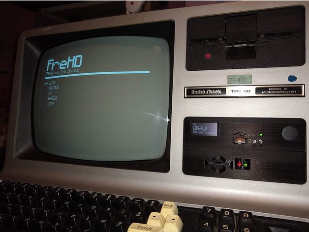
Here's photo 1. Ignore the items I've marked with an X. (I have added an internal speaker to my TRS-80, and these are the volume knob and sound-disable switch for that.) Note that in the photo there is no plastic between the two LED's poking through - The little strip between the LEDs was thin and broke when I pushed them through. This is representative of the relatively thin plastic throughout.

A thing about my (x'ed-out) audio mod that *is* noteworthy in terms of commentary on the bracket is that, when I drilled the hole for my volume knob and inserted it and clamped it down, the front panel fractured. You can see the thin horizontal line from the fracture in the photo. It's not fatal, just a thing.

1714290688896.png

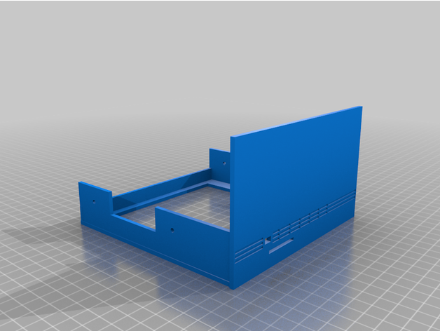
This is what it looks like from the back. You can see how it becomes necessary to put the FreHD on top. Else it's too difficult to route the hard drive cable. It should in principle be possible, but at least in my case, the FreHD cable "turns the wrong way" as it leaves the connector. This ends up making it too tall to fit below the Gotek.

(Again, ignore the potentiometer at left and switch at right. Actually, I love how my audio mods worked out, but that's a topic for another post.)

1714290947259.png

Note the blue header-to-edge-card adapter from Blue Lava. This is what you want. (Available on ebay, search for "Card Edge to IDC Connector Adapter - 5.25" to 3.5" Floppy Cable Gotek 34 pin" Link).

I had a legacy IDC-to-card-edge connector in my parts bin, but the Blue Lava adapter is superior. For one, it connects to all 17 GND lines, as opposed to the cheap one in my kit, which only picked up a couple. The other thing is its length (depth). The problem is that the depth of the Gotek and the depth of the Thingiverse bracket are similar. As a result, my legacy adapter did not extend "deep enough", and the Thingiverse bracket cross members interfered with the floppy cable card edge connector. The Blue Lava adapter provides sufficient extension in depth to allow the floppy cable to connect without interference.


Back to the full assembly, this is a photo of the FreHD cable "wrong way" thing. It creates a lot of height, that makes it not possible to put the FreHD below the Gotek. If you add a strain relief bracket to the connector, it *might* be compact enough to fit, but I doubt it. I would assert that, in general, FreHD needs to be on top.

1714291095055.png


One last caveat. You may find that you have an issue with cable length. If you mount this assembly, as your only drive, in the top bay of your TRS-80, it will not be a problem. But if you mount it in the lower bay, you may find that your floppy drive cable does not have enough length. There are two reasons for this:
  • The Gotek isn't as deep as a OEM floppy drive
  • OEM floppy drives have their card edge connectors at the top of the drive (photo below), whereas if you have used the dual Gotek/FreHD adapter as I've described, the Gotek will be at the bottom of the shared bay
1714293913327.png

The good news is that CablesOnline makes an extension adapter (FR-3404M) that makes up for the missing length. It's a bit awkward in that it leaves the card-edge connector hanging in space, but it solves the problem. I ended up buying their 4-inch extension from Amazon.

1714293045155.png

FYI for folks like me that get a 3.5" Gotek and want to adapt it to the Thingiverse bracket that I used, this is the larger display that I found on AliExpress, that works great. (if the link goes bad, search for "1.3 inch OLED module SPI I2C 128X64".) The key point is that it is a SSH1106 display.

Best of luck to all,
Brad
 
Back
Top