• Please review our updated Terms and Rules here

Mumford speedup (?) informtion

BartH

Experienced Member
Joined
Mar 11, 2015
Messages
72
Location
Netherlands
A few months ago I received a slightly battered Model 1 with a lot of satellite boards and modifications (lowercase, Level II board, new character generator, connector for external keyboard) and also an satellite board with four chips and two switches from "Mumford Micro" (a company still in existence it seems). This board was partly disconnect (it has 4 wires of which 3 were loose) but after removing it completely the M1 didn't work properly. I can only find a review in Micro-80 which states that the board has an option for normal, 2.55 Mhz and an option for 3.55 Mhz.
I would like to undo this mod, or install it properly again. Does anyone know about this board and has an instruction/installation manual for it? Most likely some modifications have been made to the motherboard as well which must been undone if I want to return the M1 to its original state.

Bart
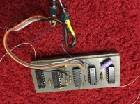
IMG_1098.jpg
 
Last edited:
Bryan Mumford is still kicking around. Maybe just ask him?

http://www.bmumford.com/

In the meantime it appears only one or two trace cuts were needed to install this, for the CLK input to the Z80. Work backwards from the CLK signal on the Z80 until you find it.

Cheers,

Ian.
 
Hmm, no luck
Sorry, I don’t have any records from 1982. It was a Mumford SK-2 Speedup Modification. I would have no idea how to hook it up or take it out.
 
Last edited:
In addition to the Micro-80 review that you found, there's a more extensive review in 80 Microcomputing February 1982 (available at archive.org) that might give you a few more hints.

E.g.: "All options require that one trace be cut and four wires be soldered to four points on the CPU. If you want software-selectable speeds, two additional wires must be soldered onto the CPU"

But like Ian says, it's most likely that the CLK input trace has been cut somewhere.
 
Last edited:
It should be fairly easy to locate thecut traces on the TRS80 board. Why not temporarily restore them and see if the Model1 will boot with the card disconnected?
 
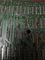
Thanks for the pointers, especially the article in 80-Micro was helpful. I found a small modification and a trace cut underneath Z34, which is the (empty) ROM socket. There are two wires, the same type as used for the lower case modification, so I'm pretty sure that reversing the mod is easy. I'll check the mods out with the schematics of the Model 1 and then remove the wires and reconnect the trace cut. Fingers crossed; I'll give you all an update!
IMG_1102.jpg
 
Thanks Ian, much appreciated since it would probably introduce new problems when removed. The most obvious trace to cut is the one between Z56 pin 8 and Z72 pin 12 and this one was actually cut, and resoldered afterwards. :confused:
To be continued....
 
Any chance you could take a picture of the solder side of the sk-2?
And another one of the top? (One of the chips is hard read)

Jim
 
Documents for the Holmes Sprinter can be found online. The installation information there may help you. I suspect that they required similar changes to the Tandy board.
 
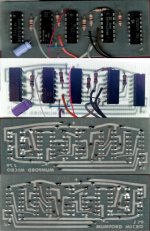
For those interested in this board, maybe even for reproducing it, I've uploaded the pictures of front and back. The chips are readable this time😊
TRS-80_SpeedUp_Mumford_1979_x4.jpg
 
Back
Top