• Please review our updated Terms and Rules here

My floppy remapper project, version 2

I would like to get one of these boards but need a little guidance on dealing with PCBWay. I really cannot make sense of their web site. Was able to find the remapper board, but from there it's unclear how to order an assembled unit.
 
OK - so I have a question... I have a Gotek and I would like to use it as an external drive and be able to boot from it.
So why couldn't I just modify the floppy cable to piggy back another termination to the external Gotek configured as device 0
then just use a switch to turn off power alternatively between the Gotek and the TRS-80 drive?
flip the switch to TRS-80 and Gotek goes off and TRS-80 drive is on - boot from it or do whatever.
Want to switch to the Gotek, flip the switch, Gotek turns on and TRS-80 drive turn off.

Am I missing something here why this wouldn't work? :)
 
OK - so I have a question... I have a Gotek and I would like to use it as an external drive and be able to boot from it.
So why couldn't I just modify the floppy cable to piggy back another termination to the external Gotek configured as device 0
then just use a switch to turn off power alternatively between the Gotek and the TRS-80 drive?
Because external connector does not have drive select signal for drive 0.
 
Hi George,

I wouldn't be using the external connector. I am expanding the internal floppy ribbon with another device. The ribbon would continue out through the opening at the bottom of the computer.
So, I would have two device 0: on the same cable (internal and external) and contention would be eliminated by switching the power on/off on each.
 
Hi nopizzatonight,

Yes, I think that should work. I'm not sure if you'd need to switch both 5v and 12v power, or just the 5v. Alternatively, you can wire up a switch for the single drive select 0 line (since you are making a new cable) instead of messing with power.
 
Thank you - you are right :) LOL - don't know why I was over-complicating it with power.

In the end I 3D printed a face plate for my Gotek and put a switch on it to alternate between the top drive and the Gotek below alternately as drives 0: and 1:
I saved the bottom drive as a spare in case something ever goes south with the drive currently in the system :)
 
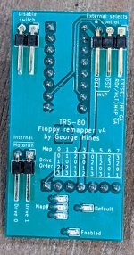
Version 4 of my remapper is now up on github


front-v4.jpg

Changes:
  1. Added support for controlling MotorOn signals. Thanks to Pete (pski) for this suggestion!
  2. As I had to reduce the number of LEDS (for MotorOn), I simplified how the current MAP is displayed
  3. Increased passive component size to 0603 for easier assembly (and verification)
  4. Tweaked the silkscreen to make the text more readable
  5. Fixed LED brightness (because these things matter)
Note: One user has reported some strange behaviors that I (hope) are not related to my board. However, you never know! I'll post more as I learn more.

Best regards,
 
Version 4 of my remapper is now up on github


Changes:
  1. Added support for controlling MotorOn signals. Thanks to Pete (pski) for this suggestion!
  2. As I had to reduce the number of LEDS (for MotorOn), I simplified how the current MAP is displayed
  3. Increased passive component size to 0603 for easier assembly (and verification)
  4. Tweaked the silkscreen to make the text more readable
  5. Fixed LED brightness (because these things matter)
Note: One user has reported some strange behaviors that I (hope) are not related to my board. However, you never know! I'll post more as I learn more.

Best regards,

I'm probably that user and have been remiss in following up on my testing. Once the H-11 is off the bench I hope to get back to it. Thanks again for all your work on this.
 
If you just want one, pm me and I'll hook you up. I have two left.
I want to also get a few of them built (maybe 5). I've also tried to go through PCBway but they are asking for a 'pick & place' file? Being a chip guy I naturally have no idea what that is. Can you advise on this? Thanks, by the way...very cool project!! Thanks.
 
If you ask a company to produce a bare board for you ("PCB"), you will need to supply them with the gerber files. These are files that define the layers that make up the board, and holes (if any) in the drill file / drill files.
If you ask the company to also assemble the components and produce a finished (hopefully) working board ("PCBA") you will also need to supply the list of components (bill of materials - BOM) and a file which tells the position, orientation and side of the board (if the board has components on both sides) for every component. This is often called the pick and place file, or POS (position) file.
 
Version 4 of my remapper is now up on github


View attachment 1210806

Changes:
  1. Added support for controlling MotorOn signals. Thanks to Pete (pski) for this suggestion!
  2. As I had to reduce the number of LEDS (for MotorOn), I simplified how the current MAP is displayed
  3. Increased passive component size to 0603 for easier assembly (and verification)
  4. Tweaked the silkscreen to make the text more readable
  5. Fixed LED brightness (because these things matter)
Note: One user has reported some strange behaviors that I (hope) are not related to my board. However, you never know! I'll post more as I learn more.

Best regards,

I bought a couple of these off ebay but have been unsuccessful getting them to work in my Model 4D (which is a model 4 gate array). I socketed U79 (where the remapper is installed) and U95 (in order to lift up pin 1 to jumper it to the EXTSEL connection at the top right. The machine works fine with it not installed (just putting the original chips in the sockets), and it works fine with it installed too, but the remapping doesn't seem to work and the remapper flashes the LEDs alternating the flashing the three Map# LEDs with flashing the Enable+Default LEDs. Whether or not I jumper the disable switch pins makes no difference. Out 244,1 and out 244,2 do momentarily enable the drive motors of drive 0 and 1 respectively, but out 244,7 for example does not change the drive map to switch drives 0 and 1 around. It seems no matter what I do the LEDs just flash alternately as described. Both of them behave exactly the same so I must be doing something wrong.. any idea what? btw.. if I power it up out of circuit with just VCC and ground it does the exact same thing. I don't own a programmer for these unfortunately and buying one seems like putting good money after bad.
 
Last edited:
Hi view836,

Sorry you are having trouble. I don't think you have done anything wrong.

It sounds like both boards are running into a self test failure. See:


When the pic is first programmed, and it boots for the first time, I have it do a post-programming self check. If it fails, it is not recoverable without reprogramming. As I extensively tested the sw image before posting it, I doubt it is a sw problem (assuming it is using my image). Rebooting won't help as the sw has found a hw problem and will not run the self tests again.

If you bought this from someone, I would recommend that they always boot the device once after programming (outside of the computer) to ensure the self tests validate the hardware.

This is only done once, and has a clear pass / fail indicator. After this, the board should work with a very high probability. After all, this is the point of the tests. Although, I'd even further recommend they test it in a computer as a final check. However, the self test extensively checks all of the boards functions.

So, if you don't want to go down the rabbit hole of debugging the boards and reprogramming them, you might try sending them back to the seller to have them sort it out. If you want to attempt this yourself, I have provided information on github to help.

The good news is that the board isn't complicated. The fact that the leds are flashing is a good sign. The pic is clearly working, the leds are installed correctly. I'd first cross check the pic part number against the bom to make sure the right part was used. All of the traces can be checked, and there are only a few passive components.

However, regardless of the problem, (again assuming you are seeing a self test failure), reprogramming will at a minimum be needed.

Best and HTH,
Thanks that's very helpful. I took a look at the source code (from github) and it looked exactly as you explained it. I'll try to get my hands on a programmer, all my PIC stuff is from the ICD2 era and won't work with more recent tools and devices. Moral of the story, do the first power on self test on the bench after programming. :)
 
Great, I will try to help as much as I can. Unless the Pic is damaged, installed incorrectly, or the wrong/fake part, it probably will work after reprogramming. However, I offer no guarantees!

And yes, that is the intent of the self-tests. They are designed as a one-time, post-manufacturing, post-programming board validation. It avoids the headache of having to manually test every function/pin. A lot of the code in the main.c is devoted to the testing feature.

Best of luck!
I acquired a pickit4 and was able to reprogram the devices, and run the self-tests successfully.

In case people encounter this thread facing a similar challenge of needing to reprogram their devices, I will offer a couple things:

- the new in box pickit 4 would talk to the computer and MPLAB tools but would not properly interface to the PIC, it didn't supply voltage to the device. I then focused on just getting it to Read Device ID in MPLAB IPE as being the simplest test of 'these things talk to each other'. I found that IPE provided clearer status information about the connection with the pickit4 and device than the IDE did. Ultimately to get it to work I had to invoke the Bootload Mode in the pickit4 and update the pickit4 firmware in MPLAB IPE, after which everything worked perfectly on the first try. It was a frustrating initial half trying to understand why nothing would work, it seems it was a versionitis thing between the latest MPLAB tools and the out-of-the-box pickit4 firmware.

- for simply reprogramming and then testing these device the simpler interface of MPLAB IPE works much better than the IDE for programming this device. I selected the target device type and went to advanced mode to get it to power the device, made sure Read Device ID worked, imported the hex file and programmed the target device. Programming multiple devices was then extremely easy. With the hex file loaded I could program the PIC, then select Settings>Release from Reset to allow the self-test to run to completion, then select Settings>Hold in reset and switch to the next device to program. Super easy and super fast.

Thanks for your help!
So glad it worked and thank you for sharing your tips!!!

Best regards,
 
For what it is worth, I am very pleased that "Tucs Workbench" on eBay is offering my remapper boards for sale. Hopefully, this initial programming/testing gotcha is now a thing of the past. It is definitely something to watch out for, should you want to make your own.

This is the benefit of sharing the design on github. It is there for anyone to use. I've run out of my extras, so am glad that there is interest and a means to purchase them ready made. It definitely avoids the hassle of making them yourself, and the extra cost if you only need a few.

Thank you Tuc!
 
Back
Top