• Please review our updated Terms and Rules here

My floppy remapper project, version 2

I would like to get one of these boards but need a little guidance on dealing with PCBWay. I really cannot make sense of their web site. Was able to find the remapper board, but from there it's unclear how to order an assembled unit.
 
OK - so I have a question... I have a Gotek and I would like to use it as an external drive and be able to boot from it.
So why couldn't I just modify the floppy cable to piggy back another termination to the external Gotek configured as device 0
then just use a switch to turn off power alternatively between the Gotek and the TRS-80 drive?
flip the switch to TRS-80 and Gotek goes off and TRS-80 drive is on - boot from it or do whatever.
Want to switch to the Gotek, flip the switch, Gotek turns on and TRS-80 drive turn off.

Am I missing something here why this wouldn't work? :)
 
OK - so I have a question... I have a Gotek and I would like to use it as an external drive and be able to boot from it.
So why couldn't I just modify the floppy cable to piggy back another termination to the external Gotek configured as device 0
then just use a switch to turn off power alternatively between the Gotek and the TRS-80 drive?
Because external connector does not have drive select signal for drive 0.
 
Hi George,

I wouldn't be using the external connector. I am expanding the internal floppy ribbon with another device. The ribbon would continue out through the opening at the bottom of the computer.
So, I would have two device 0: on the same cable (internal and external) and contention would be eliminated by switching the power on/off on each.
 
Hi nopizzatonight,

Yes, I think that should work. I'm not sure if you'd need to switch both 5v and 12v power, or just the 5v. Alternatively, you can wire up a switch for the single drive select 0 line (since you are making a new cable) instead of messing with power.
 
Thank you - you are right :) LOL - don't know why I was over-complicating it with power.

In the end I 3D printed a face plate for my Gotek and put a switch on it to alternate between the top drive and the Gotek below alternately as drives 0: and 1:
I saved the bottom drive as a spare in case something ever goes south with the drive currently in the system :)
 
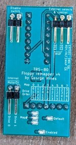
Version 4 of my remapper is now up on github


front-v4.jpg

Changes:
  1. Added support for controlling MotorOn signals. Thanks to Pete (pski) for this suggestion!
  2. As I had to reduce the number of LEDS (for MotorOn), I simplified how the current MAP is displayed
  3. Increased passive component size to 0603 for easier assembly (and verification)
  4. Tweaked the silkscreen to make the text more readable
  5. Fixed LED brightness (because these things matter)
Note: One user has reported some strange behaviors that I (hope) are not related to my board. However, you never know! I'll post more as I learn more.

Best regards,
 
Version 4 of my remapper is now up on github


Changes:
  1. Added support for controlling MotorOn signals. Thanks to Pete (pski) for this suggestion!
  2. As I had to reduce the number of LEDS (for MotorOn), I simplified how the current MAP is displayed
  3. Increased passive component size to 0603 for easier assembly (and verification)
  4. Tweaked the silkscreen to make the text more readable
  5. Fixed LED brightness (because these things matter)
Note: One user has reported some strange behaviors that I (hope) are not related to my board. However, you never know! I'll post more as I learn more.

Best regards,
I'm probably that user and have been remiss in following up on my testing. Once the H-11 is off the bench I hope to get back to it. Thanks again for all your work on this.
 
If you just want one, pm me and I'll hook you up. I have two left.
I want to also get a few of them built (maybe 5). I've also tried to go through PCBway but they are asking for a 'pick & place' file? Being a chip guy I naturally have no idea what that is. Can you advise on this? Thanks, by the way...very cool project!! Thanks.
 
If you ask a company to produce a bare board for you ("PCB"), you will need to supply them with the gerber files. These are files that define the layers that make up the board, and holes (if any) in the drill file / drill files.
If you ask the company to also assemble the components and produce a finished (hopefully) working board ("PCBA") you will also need to supply the list of components (bill of materials - BOM) and a file which tells the position, orientation and side of the board (if the board has components on both sides) for every component. This is often called the pick and place file, or POS (position) file.
 
Back
Top