• Please review our updated Terms and Rules here

Mystery Serial Card (Microtek SV622)

onesimus

Experienced Member
Joined
Jan 15, 2023
Messages
144
Location
Turtle Creek (Madison), West Virginia
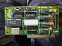
Hello! I ended up with this serial card on eBay, hoping I could save a few bucks and not have to get a Super Serial Card. Unfortunately, I did not do sufficient research, because as I have found, there is next to nothing about this card online. While it's definitely a serial card, based on my research, there is at least one source saying it's a parallel card. It's definitely a serial card, though. The worst part is that the jumper settings are nowhere to be found online, explaining why it was cheaper.

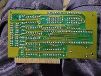
I was just wondering if any of you guys have any experience with this card or perhaps know of some archive where the jumper settings are that I can't find. I will include photos.

It is a "Microtek Slotware SV622" made in 1983. There are a couple of other numbers on it, one of which says "DRW. 300-10455 REV. B." After searching both of thees to the best of my ability, I can't for the life of me find the dip switch settings. If any of you guys know anything about this or know of where these settings might be, I would be incredibly thankful, as I'm trying to get my Apple IIe online and perhaps even use it in my IIGS with the AppleSqueezerGS.

May the light of Christ shine in your lives!
 

Attachments

  • 20240311_140817.jpg
    20240311_140817.jpg
    4.1 MB · Views: 26
  • 20240311_140830.jpg
    20240311_140830.jpg
    4.9 MB · Views: 25
  • 20240311_140844.jpg
    20240311_140844.jpg
    3.3 MB · Views: 26
Note that the switches are just the default settings and your communications client should be able to change the settings, especially if the firmware is SSC compatible. It appears that there are only 7 pull-up resistors per bank of switches, so you are right back in line with the SSC switches, with one switch from each of them being unused. It is hard to see, but based on where the data lines appear go, the function of the switches generally appears to be consistent with the SSC too.

You can look on the front and back of the board and see which switch is not connected to the black resistor network, and ignore it. Then the remaining ones are probably the same as the SSC.

If all else fails, It should not be too hard for you to follow the traces or use a continuity tester from switch 1 and 2 to U1 and U2, then from U1 and U2 to U5. Then compare with the R6551 data sheet register location and pinout.
Thanks for the info, good stuff. I'm not quite as proficient with board level components like you are, I wish I were and hope to get there someday, so this is great to know. Sounds like it might just be an SSC clone, for the most part, in that case. I would imagine just setting the SSC switch settings and ignoring the last switch on the bank would probably work.

Also, great to know about the program generally be able to change the settings and even override the switches. This info might just save the day for my Apple II networking needs! Especially since it's looking like an SSC clone (more or less, not necessarily an exact clone).
 
It appears that there are only 7 pull-up resistors per bank of switches, so you are right back in line with the SSC switches, with one switch from each of them being unused.
Shoot, on second look, I was wrong about that. there are actually 9 pull-ups. But, I am still thinking that where the data bits go looks similar to the SSC switch layout.
 
Shoot, on second look, I was wrong about that. there are actually 9 pull-ups. But, I am still thinking that where the data bits go looks similar to the SSC switch layout.
I've gone ahead and set some basic modem settings for the SSC on my card, leaving the additional switch off. I'll try to report back tomorrow with the findings.
 
Back
Top