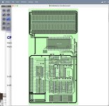
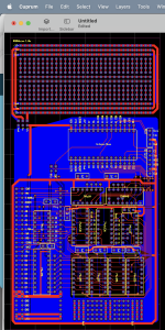
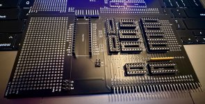
I have designed a PCB for putting an Arduino Nano on the NABU's expansion bus. It aims to provide several functions:
* An SD card interface, with the Arduino handling the FAT formatting of the SD card; and making blocks available to the NABU's CPU from within raw disk images - I figure that a modification to the boot ROM of the NABU will be needed as well as a simple BIOS for CP/M.
* A PS/2 mouse port. I added this because I'd like to build a paint program.
• Prototyping area for tinkering. I laid out a perf-board style area with breadboard style bus routing for power (5v & 12v) and ground lines; and there's also 8 unused pins on the Arduino Nano that can be used to shuttle signals to/from the NABU.
As my NABU hasn't arrived yet, I've been working from just the technical documentation available online; so this is totally preliminary... but, after I get it minimally tested (basically, no magic blue smoke escapes and I can send/receive data to/from the card) I intend to release the Gerbers on GitHub so that anybody can make one.
All the chips used are common, ubiquitous logic ICs, and available from the usual sources (DigiKey, Mouser, etc). Other parts needed are easy to source from eBay: female SIP sockets, DIP sockets, an Arduino Nano (or clone), some decoupling capacitors for the logic ICs (the PCB has pads for 5mm lead-spacing caps and is marked for 1uf - but any ceramic capacitor in that range will do), and a bussed resistor pack to keep the data bus on the NABUduino side from floating.
The bus interface implements two write registers and three read registers (as viewed from the perspective of the Z80). The address line mapping on the board puts these at offsets 0x08, 0x09, and for the read-only register 0x0A. The intent is that the high byte register be used as the command opcode or result status, and the low byte register be used as the arguments (or data) for a command. The read-only register exposes a couple of flip-flops that are used to synchronise the transfer of data between the Z80 and the Arduino (the bits get set when one side writes data to a register and cleared when the other side reads it, allowing the next byte to be sent). The low-byte registers' read and write signals also can be connected to the interrupt-capable pins of the Arduino with a pair of jumpers - although I anticipate that usually they would be connected; I did leave the option to disconnect that so that one or both interrupts could be used for something else.
Also, one of the Arduino pins is connected to the INT line on the NABU expansion interface, should one need to interrupt the Z80 for any reason.
There are several unused gates in the logic ICs on the board (two SR flip-flops, three inverters, and two OR gates); I tied the inputs to the gates to ground thru some easy-to-cut 0.01" traces; and also added pads adjacent to the chip to allow adding jumper wires to use the gates, if desired. Also, the unused address decode lines are also routed to pads, so that additional registers or other functions could be added in the prototyping areas.
The board is 85 x 165 millimeters, so it should fit nicely in the case of the NABU, only occupying one slot's worth of space. Not having a machine on hand to measure, however, does mean that I will still need to add mounting holes somewhere on the board - currently you'd have to depend on the female socket for the expansion header to hold the board... clearly not ideal if you want to have anything else in the machine besides a single NABUduino board.


