• Please review our updated Terms and Rules here

Need help with RTC on Intel Above Board PS/PC

dhau

Experienced Member
Joined
Feb 13, 2018
Messages
323
Location
Toronto, ON, Canada
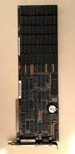
Hi folks, I am using an Intel Above Board PS/PC (PS = Parallel/Serial ports, PC = classic bus aka 8-bit ISA).

Intel Above PS-PC 1280 pixels.jpg

It is a multi-function board for XT-class computers. It has 1.5MB ram on it: 6x9 41256 DRAM chips. It can be used as either EMS or to backfill conventional RAM. It works fine, EMS passes Intel and Borland tests fine. I didn't test parallel, but mouse works fine on serial port.

The problem is there is no software to set/get date/time. The RTC chip is OKI m6242. It is easy to find the datasheet for it. It can work in either dual port (control/data) mode, or in 16 port mode where all the RTC registers have direct read write. I assume on PC Intel will use dual port setup.

Is there a way to somehow detect what those ports are? I know Plasma's Turbo XT BIOS somehow detects ports. I'm not great at reading assembly code. Can someone give me an idea how to detect working ports on a XT-class PC? Pseudo-code, Pascal, C, BASIC, anything would be greatly appreciated.

If I will find out the ports, I'll try to read and write to registers as per datasheet.
 
Hey, did you ever figure out how to access the clock on this card? I just picked one up and haven't had success with any of the clock programs that I've tried.
 
I didn't yet, and probably won't any time soon. But check back in a few months. If I'll figure it out, I'll post an update in this thread.

So far I can tell that Quadram Quadboard also has an OKI RTC chip, although an older one: MSM5832. Quadmaster, the software bundle for Quadboard, came with some BASIC examples. I'm looking at those programs now for some ideas.

Datasheet for MSM6242B: https://www.alldatasheet.com/datasheet-pdf/pdf/11259/OKI/MSM6242B.html
Datasheet for MSM5832: https://www.alldatasheet.com/datasheet-pdf/pdf/11250/OKI/M5832.html
 
Success! Grab this file: intel_above_board_v40a.zip. Extract clock.sys. Add the line to your config.sys:

DEVICE=path-to\clock.sys

Reboot. Now set the right date/time with DOS commands date and time. It seems like clock.sys is syncing with DOS clock continuously. If you reboot again, you should see the PC keeping the time now.

The bad part is that clock.sys eats 1280 bytes of conventional memory. So I'll still try to make a get/set date/time program.
 
I am stoked to finally find the CLOCK.SYS for this board! Any luck making a get/set program?
Some RTC solutions only have one supporting file, CLOCK.SYS
At boot time, when CLOCK.SYS gets loaded, CLOCK.SYS will set the DOS clock from the RTC solution.
Later, at the DOS prompt, using the date and time commands of DOS will result in CLOCK.SYS updating the clock in the RTC solution.
 
it used some old style coin battery, but a regular 2032 sort of fits fine. It is a bit smaller and fatter than original, but it's fine.
 
Any luck making a get/set program?

So... the GLaTICK ROM I posted about the other day does that. It uses an option ROM to provide BIOS level support which means software or drivers are no longer needed. Just needs a way to put the ROM in the PC somehow so the BIOS can see it.

Now, the MSM6242 isn't supported yet, but it's on my list of cards to get so that it can be added. There's one on eBay right now and if I win it, I'll add support for it if there's interest to try it! :)
 
it used some old style coin battery, but a regular 2032 sort of fits fine. It is a bit smaller and fatter than original, but it's fine.
Thanks. I gave it a try, but get a msg 101 (Clock hardware isn't working) message. Do you think the problem is the battery, or something else?
 
Thanks. I gave it a try, but get a msg 101 (Clock hardware isn't working) message. Do you think the problem is the battery, or something else?
At [here] is what appears to be switch setting details of the card. Note that one of the switches enables/disables the clock functionality. In the disabled position?
 
At [here] is what appears to be switch setting details of the card. Note that one of the switches enables/disables the clock functionality. In the disabled position?
I bet this is the problem -- I did see these settings on Stason, but as I re-review it now, I see my brain assumed SW1 was on the left side and SW2 on the right, but it's actually reversed. Looks like I flipped the wrong switch. I'll try it again this weekend when I have some time to play with it again. Thanks!
 
Can you post a photo of your board? Does it have OKI m6242 RTC chip?
Thanks for the help. I can't quite tell what type of RTC it is. But I did try adjusting the dip switches again, with no luck. Just the same 101 error. I'm guessing it's probably just broke, but luckily the rest of it works okay.


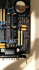
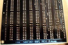
IMG_0019.jpegIMG_0020.jpegIMG_0021.jpeg
 
Sorry to say it, but you look to have inserted the battery the wrong way. It should have the letters on the visible side, and yours seems to show "belly" with no letters.

I hope this didn't damage the circuit.
 
Thanks for the help. I can't quite tell what type of RTC it is. But I did try adjusting the dip switches again, with no luck. Just the same 101 error. I'm guessing it's probably just broke, but luckily the rest of it works okay.

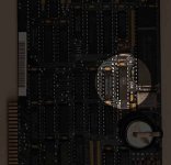
oki_2.jpg


Yes, it does have an MSM-6242 - see highlighted.
 
Sorry to say it, but you look to have inserted the battery the wrong way. It should have the letters on the visible side, and yours seems to show "belly" with no letters.

I hope this didn't damage the circuit.
I couldn't tell which way was right, but did originally have it the other way. I hope it didn't damage the circuit either!
 
Back
Top