vanderk
Experienced Member
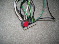
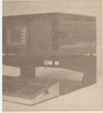
Hi. I recently pick-up a monitor stand (Porta Micro Mate) made in the 80s by SOS computers that was designed for the Commodore 64 and Kaypro computer. It is very functional but the surge protector and switches were not wired at all (appears someone disassembled the stand at some point and unplugged the wiring at the surge protector circuit). I'm not entirely sure how to plug in the hot, neutral, and ground spade connectors in combination with the Varistor on the board.
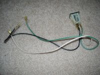
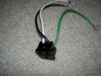
- There are 5 hot, 5 neutral, and 5 ground wires (2 switches, 2 outlets, and one AC plug)
- 15 spade connectors are on the board; connectors are connected in pairs and groups of three and some of these pairs/groups are also connected via traces
- Two screw holes are connected to a group of three spade connectors in the center
- Two pair of spade connectors are "floating" and simply soldered to the board
Can anyone please help me with this puzzle? I am a ham operator and used to working around AC, DC, and HV wiring; but this one has me a little stumped. Thank you!
The Varistor goes to a pair of spade connectors on one side and three spade connector on the opposite side.
P.S. Pushing the "computer" or "monitor" button shorts neutral and hot (I believe these are wired correctly). I am assuming the two screw holes and spades connected via traces to the holes go to ground, but I wind up having two extra ground wires not connected.
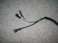
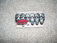
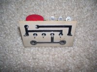


Last edited:

