• Please review our updated Terms and Rules here

Newly acquired 11/23+

azog

Experienced Member
Joined
Apr 19, 2004
Messages
143
Location
New Jersey
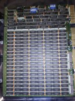
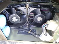
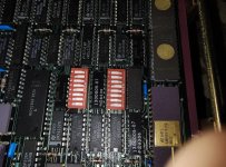
So I acquired an 11/23+ and am in the process of assessing and inventorying it. I haven't powered it on (I like to think I know better than that), but as I am examining the chassis, I am struck by how clean this thing is. It looks like it was barely used, no dust or other crud that tends to build up. See the images of the fans, they look almost factory fresh. And an image of the CPU board; I took that mainly to document the DIP switches, but the cleanliness is encouraging.

I did find some documentation on the power supply (H7861), but it looks rather intricate to uncouple it from the chassis, backplane, etc. So before I try, I wanted to ask around for any advice on what to look for, any prime candidates for trouble, things like that.
 

Attachments

  • IMG_20240819_155728554.jpg
    IMG_20240819_155728554.jpg
    258.3 KB · Views: 43
  • IMG_20240819_155846354.jpg
    IMG_20240819_155846354.jpg
    361.4 KB · Views: 43
Depending on the chassis and power supply, is there a voltage selector on the beast to check?

Then the usual RIFA capacitors...

I would document exactly which cards are in what slot (and half slot), and (if you are going to power it up) remove all the cards and power up the empty chassis first.

This will protect your cards if anything goes wrong with the power supply.

Dave
 
If it's a BA11N or S then the power supply flips down on two spring hinges and can come off. I've had to repair one, they are not really too complicated IMO.

Fire it up as Dave says, just have a small fire extinguisher handy. Then check the voltages and if they look good power down and pop the CPU+memory in and see if the serial port comes alive. Go from there.
 
Of course, you just need the CPU and a serial console port to get ODT operational. No memory required.

You can't do much with it though, but it is the most minimum system for a test. Is the serial console port on the CPU board? I can't remember now, and I am on my phone.

Dave
 
I found two screws that let the whole front panel w/ power supply drop down, so I can examine it. The worst visual offender is all the foam padding has disintegrated. Internally the power supply visually looks fine. I didn't spot any infamous RIFA caps but maybe I'm short sighted. The electrolytic caps are intact, no leaks or bulging cans. I'll bring home some anti-stat bags from work tomorrow, so I can pull the cards and power test. All the voltage rails are nicely marked, so I can test it and maybe burn it for a day or so, Just In Case.

It also allowed me to inventory the config, top down:

* M8189 - CPU with FPU; yes, it has two serial ports on-board, one for console
* M8067 - Marked KF? 256k? Half the RAM sockets are unpopulated
* an unmarked card with four black handles, can't tell yet
* M8061 - RLV12 disk controller
* M8043 - DLV11-J 4 serial ports
* M8017 - DLV11-E single serial

Dunno what the third card is but I guess I'll get a better idea when I pull everything out.
 
Hi, your PSU will be an H786, or H7861 if it was a real 11/23+ system - there are two huge mains smoothing caps that you need to not surprise with 240V after many years being turned off.. They would benefit from reforming (charging very slowly over an hour or more) or if nothing else, power the chassis up with no boards via a 40w or 60w tungsten mains lamp (it will flicker repeatedly) and let them get used to being capacitors again - better still, a variac to start it up slowly.

Once it has run for an hour or more, a 100W bulb should get the output voltages showing, you need some load on the +5V to get the +12V to regulate...

Mind your fingers in the metal fan blades - ad of course, most of the PSU is at live mains voltage - be careful!

Photos of the unmarked card would be interesting!

Oh the foam under the PCB - I had one were it was just sticky gunk and scraped it all off and put some suitable size rubber feet on the chassis under the PCB to support it and stop it flexing so much...

The PSU will need a good long test, I would suggest - mine gained a couple of faults in the first couple of days of use

Robin
 
I see in the photo of the CPU it has the original KDF11-BA boot ROMs (23-339E2 and 23-340E2). This board can be upgraded to the latest KD11-BJ version by replacing them with the 23-453E4/23-454E4 ROMs. These ROMs are a little unique in that they are 8K byte EPROMs but in 24-pin packages (Motorola MCM86766). If you swap for these ROMs, you have to switch position on the jumper in the lower left corner of the module (near the ROMs, near the Qbus fingers). The latest ROMs have a lot more boot device support.

If you can't find those rare EPROMs, Retro Innovations (www.go4retro.com) makes an adapter that will let you use regular 2764 EPROMs.
 
Last edited:
thanks for the advice re the boot ROMS. I will certainly look into that. The system came with a pair of RL02s, but I haven't touched or looked at them yet.

The power supply is indeed a H7861. I've been reading up on reforming caps. Looks easy enough. Hopefully those big mains filter caps aren't soldered.

As for the "mystery" board, it is a Camintonn CMV-1000, which is a 1mb memory board (https://gunkies.org/wiki/Camintonn_CMV-4000)
 

Attachments

  • IMG_20240820_144143806.jpg
    IMG_20240820_144143806.jpg
    284.7 KB · Views: 18
Hi - yes the two big caps are bolted to the board, once the board is out, they are easy to remove... also - check/redo the soldering on the DC output terminal block, and if you have it removed, the backplane... but don't undo the backplane unless you need to - you have to manually get the card guides to line up with the connectors to reassemble - a quad board or two is ideal for this to get the position correct...

Take care reforming, something like 100K and 100 - 200 volts DC to slowly charge them is ideal, BUT THEY WILL HOLD CHARGE without the balancing resistors on the PSU and are DEADLY!!!

Ideally, you want an (insulated) changeover switch to select between charging and discharging and a meter connected. You can do them both in parallel at once.

I started an even older H786 using the series bulb method and let it sit for a couple of hours and it was OK, but you never know!

Robin
 
I th
thanks for the advice re the boot ROMS. I will certainly look into that. The system came with a pair of RL02s, but I haven't touched or looked at them yet.

The power supply is indeed a H7861. I've been reading up on reforming caps. Looks easy enough. Hopefully those big mains filter caps aren't soldered.

As for the "mystery" board, it is a Camintonn CMV-1000, which is a 1mb memory board (https://gunkies.org/wiki/Camintonn_CMV-4000)
I think I have this same memory module installed in my 11/53. As I recall, the jumpers and settings are essentially identical to the equivalent DEC module (MSV11-QA).
 

Attachments

Last edited:
Wow, I have the same memory board in my Calay PCB layout system which is in an SMS 11X chassisIMG_5651.JPG
 
I have a number of 3rd-party memory boards containing both 64K and 256K DRAM devices. There are subtle differences in the cards (and the devices themselves).

For example, the 4164 has a NC (No Connect) on pin 1. The 41256 has pin 1 as an extra multiplexed address line (A8). Unless the PCB has been wired up for the extra address line - you will have to do a bit of 'hand wiring' and add an extra address multiplexer.

The largest difference is the address decoding. On the cards that I have, this is all done (largely) inside a PAL - but there are a few associated link differences.

Not impossible (I remember double-stacking 4116 devices back in the day and wiring up the CAS line to a bit of additional decode logic).

Dave
 
I got the same system more or less a few months ago, it was just as clean so you are probably good. The advice i was given on here was run the xxdp tests on the boards to get a clean bill of health first. I got lucky and everything is working and stable except one of the RL02 drives won't latch.
 
So after spending time reforming the CPU box power supply, and burning it in for several day, I finally did a smoke test of the CPU board and 256k memory.

The diagnostic lights (image attached) show "off - Power - on - off - off", according to the manual (EK-245AA-MG-001, table 3-1) means the basic system diags passed. But I cannot get anything from the console. I've verified my cabling a dozen times, and checked the default switches and jumpers (figure 1-1 and table 1-3 in the same manual). A scope on the console pins show no activity. This weekend, I plan to build a franken-cable, just three loose wires (tx, rx, gnd) that I can run and visually verify, but I wager I won't get any different results.

I notice that the power LED on the diagnostic LEDs seemed a bit dim, so out of curiosity, I checked the 5v rail, and it measures a steady 4.9v. Not sure if that is too low or what.

So currently stalled, not sure what to do. I recall reading "somewhere" about calibrating the H7861 power supply, but now I can't find the info. The other possibility is the UARTS. Sadly they're not socketed, and I really dread the idea of using a desoldering station on this thing.

IMG_20240829_153247376_HDR.jpg
 
Back
Top