• Please review our updated Terms and Rules here

No place on 286 for external battery, no battery on board?? Losing CMOS all the time!

joebelter

Experienced Member
Joined
Jan 22, 2025
Messages
59
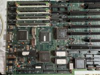
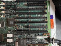
I'm finally getting my Everex TEMPO 286/12,16 (EV-1824(C) up and at least running in Dos 3.3 from a floppy. Unfortunately there's no place on the board for an external battery, and no place ON THE BOARD for a barrel battery or something.
There's no Dallas, nothing. So each time I try something if I turn it off for more than a few minutes I'm back to setting it up again... Neither the Retro Web or Stason has setting for jumpers for battery settings.
Any ideas where I can put 4.5 volts so I don't have to do this?
Here's a pic of my board for reference:

Thanks in advance!
Joe
 

Attachments

  • left.jpg
    left.jpg
    291.6 KB · Views: 42
  • right.jpg
    right.jpg
    305.9 KB · Views: 41
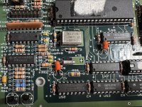
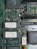
My guess is that the cylindrical crystal XT5 in the lower left corner is the 32.768 KHz RTC clock crystal. Can you get a zoomed in photo of that corner of the board with legible part number markings on the ICs in that area?
 
I've tried putting my 4.5v battery on J24 in different combos (since there's 3 pins always watching the "+" sign) but that doesn't help.
Hopefully these photos help.
Appreciate the help here!
 

Attachments

  • clock1.jpg
    clock1.jpg
    254.3 KB · Views: 36
  • clock2.jpg
    clock2.jpg
    281.8 KB · Views: 36
Is this the kind of thing that with a multimeter can be worked backwards from a particular pin on the chipset?
 
Well that doesn't sound like good news for me! Just looking through the document made me dizzy!
Why didn't these companies make some provision for power?
Is there a a utility once I get this thing running that I could perhaps WORSE case run once every time I turn it on and put in a few parameters to boot?
 
Is this the kind of thing that with a multimeter can be worked backwards from a particular pin on the chipset?
Generally no. The problem is that there will be a blocking diode on the battery connector. The diode serves two purposes. One, it ignores a battery plugged in backwards. Two, it keeps the main power supply from attempting to charge the battery.
Putting a multimeter in diode test mode has a potential for damaging the IC chips.

I've tried putting my 4.5v battery on J24 in different combos (since there's 3 pins always watching the "+" sign) but that doesn't help.

J24 looks like the correct connector. The + pin should connect to the unbanded side of a diode. The part marked 5817 is a diode and a good possibility. A mutimeter should show a low resistance between the + pin and the diode. It looks like R59 is part of the circuit so low resistance means 1000 ohms. The banded side of the diode should show +5 volts when powered up. Since you say connecting a battery to j24 doesn't work, you may have a leaky capacitor. Not a problem for the main power supply but will affect the battery. If this is the case there will be a voltage drop across R59 (if this is actually part of the circuit) or the banded side of the diode will show low or no voltage on battery only. A leaky capacitor (the orange components) will get hot to the touch when the board is powered up. Replacing a capacitor is possible, but not trivial.
 
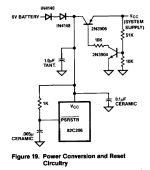
The issue is the RTC is inside the 82C206. There isn't just a "backup power" pin on it; the battery gets wired to the Vcc pin on it. There is a suggested circuit in the bottom right corner on page 40. https://www.ardent-tool.com/datasheets/CHIPs_82C206.pdf

According to the datasheet, the battery input should be 6V, not 4.5V. The specified VCC minimum voltage at the 82C206 input is 4.75V, plus there is at least one, maybe two, diode forward voltage drop from the battery input if the motherboard follows the recommended VCC power circuit.

My IBM AT had a Panasonic BR-E3 6V dual lithium primary cell battery pack. To replace that now I suppose I could get a Panasonic CR-P2 dual lithium primary cell battery pack plus a CR-P2 battery holder, or individual 3V lithium primary cells and a two cell battery holder, and remove the leads from the original dead BR-E3 and wire them up to the battery holder.


Power_Conversion_and_Reset_Circuitry.png


82C206_Operating_Conditions.png
 
There is a suggested circuit in the bottom right corner on page 40. https://www.ardent-tool.com/datasheets/CHIPs_82C206.pdf
Some 'expansion' on the recommended circuitry is at [here].

Well that doesn't sound like good news for me! Just looking through the document made me dizzy!
Why didn't these companies make some provision for power?
I agree with LostInTranslation. J24 certainly looks to me like where the external battery gets connected to. The two outer pins is the 'norm'.

It can be confirmed by:
1. Power off motherboard; then
2. Connect the battery, observing correct polarity; then
3. With motherboard still powered off, measure the DC voltage on the Vcc pin of the 80C206 chip. Expected is the battery voltage minus a voltage drop of say, up to one volt. Could be more.

According to the datasheet, the battery input should be 6V, not 4.5V. The specified VCC minimum voltage at the 82C206 input is 4.75V, plus there is at least one, maybe two, diode forward voltage drop from the battery input if the motherboard follows the recommended VCC power circuit.
Inadequate battery voltage does appear to be the problem cause here.
 
Are we still thinking J24 for the power pins? Put 6v between the outside ends?
I FINALLY have it all working! Woo hoo! The Lo-tech XT CF adapter I got from https://texelec.com/ did the trick.
I formatted a Transcend 2GB CF card, but I think I'll use that for something else. I used the standard C000 memory space for the ROM.
It's AMAZING I've gotten this far; I thought it was a brick!
Nice so far.
Let me know what to do, I'll try the J24 'norm' trick and report back! One interesting thing; once I have it powered for a few hours it will actually keep the settings for several hours before I lose them completely.
Joe
 
Are we still thinking J24 for the power pins? Put 6v between the outside ends?
Yes.

Let me know what to do, I'll try the J24 'norm' trick and report back!
Good. 6V nominal battery.

And with the motherboard powered off, report the DC voltage of the 82C206's Vcc pin. That may help us.

One interesting thing; once I have it powered for a few hours it will actually keep the settings for several hours before I lose them completely.

Hypothesis:

Engineers often allow for users 'changing the battery without losing the settings'.

The example of the IBM 5170 (IBM AT) is shown at [here]. When the 5170 is powered on, the '+5V switch' is feeding power to the RTC circuitry. As a result, capacitor C84 is charged to +5V. With no battery (or a very low battery) fitted, flicking the power switch to off, the charged C84 takes over powering the RTC circuitry. C84 will slowly discharge, reaching a point that no longer adequately powers the RTC circuitry. From memory, I can remove the battery from my 5170 motherboards, and the motherboard keeps its CMOS SETUP information intact for about 10 minutes.

If we look at [this], the recommended RTC support circuitry for the 82C206 chip, the equivalent capacitor is the 1.0 µF tantalum. And the RTC functionality in the 82C206 chip may draw less power than the RTC chip on the 5170 motherboard. So, maybe the combination of the 1.0 µF tantalum and the low power draw of the RTC functionality in the 82C206 chip, explains the several hours.

Your motherboard may be using something larger than 1.0 µF.

Maybe the fact that the 4.5V battery is resulting in some voltage on the 82C206's Vcc pin, is the reason.
 
OK, made up a 6v adapter, and left it overnight without power. Started up today perfectly!!!! Wonderful!
Thanks everyone for the help.
Hopefully this will help other people that have issues like this. It seems like I have board that don't have obvious pinouts for battery terminals.
Excellent! A fully working 286!
Now I'm 2/7 boards fixed! On to my XT...
 
Is there a a utility once I get this thing running that I could perhaps WORSE case run once every time I turn it on and put in a few parameters to boot?
There is actually. Search for Wangboot on this forum. It's a boot sector program I made that will auto-restore a backup of the CMOS and then ask you to provide the date and time (optional), then reboot. (Yes, I know you won't need it now. I'm just mentioning it in case someone else find themselves in a similar situation and they really won't be able to fix it with hardware.)
 
There is actually. Search for Wangboot on this forum. It's a boot sector program I made that will auto-restore a backup of the CMOS and then ask you to provide the date and time (optional), then reboot. (Yes, I know you won't need it now. I'm just mentioning it in case someone else find themselves in a similar situation and they really won't be able to fix it with hardware.)

This one runs from autoexec.bat very nice.
CMOS.COM v1.00 05-05-1999 Charles Dye
GPL Freeware Copyright 1994-1999, C. Dye.
email: raster@highfiber.com

This program is copyrighted, but may be freely distributed
under the terms of the Free Software Foundation's GNU General
Public License v2 (or later.) See the file COPYING for the
legalities. If you did not receive a copy of COPYING, you
may request one from the Free Software Foundation, Inc.,
59 Temple Place - Suite 330, Boston, MA 02111-1307, USA.
ABSOLUTELY NO WARRANTY -- use it at your own risk!


--- Overview ---

This program will save the contents of your computer's CMOS memory to a disk
file, or restore it from the file. The CMOS is a battery-powered chip which
contains the computer's clock and calendar. It also provides a small amount
of memory used for basic configuration information such as the number and
sizes of drives installed, memory size and speed, keyboard settings, machine
password, and so on.

A utility to save and restore the CMOS data is useful for two purposes.
First, the CMOS memory can be lost; this often happens when the battery runs
down. Many older machines won't boot correctly if the CMOS data is lost (it
contains necessary info about the hard drive geometry.) Having a backup copy
of the CMOS contents handy on a bootable floppy disk can save time, because
you don't have to look up the correct settings for your hard drive. (On
newer computers, the BIOS interrogates the hard drive directly to get the
settings. Losing the CMOS is less of a problem on these newer machines.)

Second, sometimes it's useful to be able to change CMOS options without
having to run the computer's setup utility. Especially if the setup program
is on a disk in a file cabinet somewhere; or for blind users whose screen
readers won't work in the BIOS setup utility. Simply save your current CMOS
data to a file, make your desired changes, and save again to a different
file. In the future, you can load the desired settings directly, without
having to go through the setup program.

This program will save and restore the commonest types of CMOS memory found
in most computers: the Motorola 146818, the Dallas Semiconductor DS1687, and
other hardware that emulates them. It will save either 50 or 114 bytes of
data, depending on the hardware. (Many similar programs only save 50 bytes.)
No provision is made for the extended CMOS used in EISA or MCA systems. (I
haven't had a computer of either architecture for years, so I can't even
begin to test code for them.) Also, no effort is made to save or restore the
clock and calendar; if you lose your CMOS, use the DATE and TIME commands to
reset the clock.

The file CMOS.S in this archive is source code for Eric Isaacson's shareware
assembler A86. Unless you plan to modify this program, you can delete CMOS.S
to save disk space. The file COPYING contains information on the GNU General
Public License; if you are familiar with the GPL, this file can also safely
be deleted.


--- Syntax ---

CMOS /SAVE [filename]

Saves the contents of CMOS to a file. The filename is optional; if you don't
specify it, CMOS.SAV will be used. (Don't type the brackets; they're only
there to indicate that "filename" is optional.) You may abbreviate /SAVE to
/S. Also allowed: /B (for Backup) or /W (for Write.) The switch character
is not important; you may use -S instead, or even just S.

CMOS /LOAD [filename]

Loads CMOS memory from a file. If you don't specify the filename, CMOS.SAV
is used. Legal synonyms are /L (Load) or /R (Restore.) After loading CMOS
from the file, the computer will be rebooted automatically so that the new
settings will be recognized.

CMOS /I [filename]

Loads CMOS memory from a file, like /LOAD. However, the machine is not
automatically rebooted. This option is not generally useful.

CMOS /VER [filename]

Verifies the contents of CMOS against a file. /C (for Compare) is a synonym.
In a batch file, Errorlevel 7 indicates a mismatch between the file and the
current contents of CMOS.

CMOS /DUMP

Dumps the current contents of CMOS to the screen (or stdout) as hexadecimal.
Useful only to hexperts.


--- Return Codes ---

Use the ERRORLEVEL command to check the return code in a batch file.

0 : success
1 : dos file error
2 : syntax error, invalid switch or filename too long
3 : not enough memory
4 : no cmos? hardware problem?
5 : invalid or corrupt file
6 : cmos write-verify mismatch. hardware problem?
7 : cmos - file mismatch
8 : bad dos


--- Data File Format ---

My CMOS file format is different from everyone else's; you can't share data
files between my CMOS.COM and SAVECMOS.EXE or ROM2.EXE. Mine requires a
special file header to prevent you from trying to load, say, AUTOEXEC.BAT
into CMOS, and to guarantee file integrity.

4 bytes 'CMOS' file type identifier
1 byte 10h file version identifier (1.0)
1 byte flags: bit 7 = valid, bit 6 = extended cmos present
2 bytes bios model and submodel bytes
1 word (n) length of data (in bytes) always 50 or 114
1 word checksum of data (sum of all bytes)
1 word hashtotal of data (xor of all words)
n bytes cmos data


--- What's New ---

v1.00 05-05-1999
Cleanup for release with FreeDOS. Fix for 8086/8088 CPUs. Added
strings for VERSION.EXE. Treat nul on command line as an end-of-line.
Documented /I and exit codes. Changed license to GPL.
 

Attachments

This one runs from autoexec.bat very nice.
The problem is that it requires that you can boot DOS and that is not always possible, even from floppy. The machine would just hang during the boot process for some reason and I eventually figured out that if it can actually start to boot DOS then it can definitely load and run a boot sector program as well. So while the process to get Wangboot running is a lot more involved it's definitely worth it once it's done.
 
I use it mainly with SCSI-Controllers with enabled SCSI-BIOS and a bootable SCSI drive. Your solution needs a working floppy drive and disk, not much better.
 
Back
Top