• Please review our updated Terms and Rules here

NOVA 4/X Restoration

cullyrichard

Experienced Member
Joined
Jun 11, 2024
Messages
107
Location
Massachusetts, USA
Hi All,


I am primarily a DEC PDP-11 guy and I have done some work on PDP-8 machines more recently, but I could not say no when a complete NOVA 4/X system came up for sale. The plan is to get this machine running as a counterpart to my existing PDP11 systems and to archive and explore whatever software and files are on the hard drive that was included.

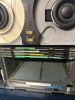
The machine is configured with a 6100 hard disk / diskette drive and a 6125 tape drive.


The Nova 4/X chassis itself is equipped as follows:

T 005 3552 R11 (dasher controller)
T 005 9973 R09 Unknown, board contains several COM2017 or equivalent UART chips
T 005-13734 R06 DISK CONTROLLER
T 005 15289 R10 TAPE CONTROLLER
T 005 12136 R06 (128K BYTE (64K WORD) RAM BOARD)
T 005 12373 R10 (FLOATING POINT UNIT)
T 005 12067 R23 (NOVA 4/X CPU W/ MULTIPLY / DIVIDE)
T 005 12061 R54 (POWER SUPPLY W/O BATTERY BACKUP)

It was built at the DG Westbrook, Maine plant, and was system #98. I am not sure what quantity these integrated systems were built or the overall total, but the construction gives the impression that there were not an abundance of these 5' tall machines out there.

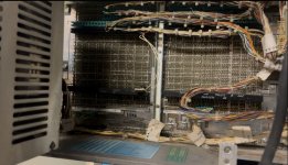
I'm working on some reforming of the large caps mounted in the rear of the NOVA 4's chassis before I apply power. These caps are nice sprague caps and they are not leaking any electrolyte so I am reasonably confident they will reform. I usually just apply power but the caps are the size of soda cans and I would prefer for them to not detonate in my basement. there are even larger caps in the hard drive that will need repair.


I'm curious if anyone has any thoughts or knowledge to share on this machine. I have been in contact with Bruce at novas are forever and I've been scraping the internet for every related manual I can find. I'm excited to get this project under way and revive a NOVA to share with the world. I also plan to release a video series documenting the progress
 
At the North American Rockwell Autonetics Division, NOVAs were used in many projects including simulating the Space Shuttle’s AP101 Computer I/O Processor.

This system was used in the Rockwell Space Division’s development lab for many years from the mid 1970’s as the IBM AP101 computer hardware was not yet available. Later a similar system was used at the Stennis Space Center in Bay St. Louis, Mississippi to conduct testing of the Shuttle main engines. The three engines along with the External Tank were mounted on a huge test stand with the NOVA 1/4 mile away in a bunker. That NOVA was a NOVA 840, a predecessor to your NOVA/4.

I am looking forward with great interest to following your restoration.
-dave_m
 
Update:

I applied power after some light reforming of the capacitors, no caps exploded and all of the voltages were within spec. The clocks work.
The machine appears to be working with the cards installed however it appears I am missing the console cable, so I’m looking to make one to hook up to a VT100 (I know, sacrilege!) or computer for the console. I do not seem to be able to locate a pinout but a backplane diagram may be of assistance.
 
When I was working at AEDC in 79-81, we had a spectrometer with a Nova. The boot had to be toggled in manually. I couldn't do that, because that was a union job. I also found out that turning on its vacuum pump was a union job (I got written up).
 
Can you share photos of "T 005 9973 R09 Unknown, board contains several COM2017 or equivalent UART chips" which presumably is where you'll need to determine the pinout? What is labeled by the left handle on the board? What is the board ID labeled by the right handle? I'll wager that it's "SYNC-ASYNC CONTROLLER" that may only have the four ASYNC channels populated.

It's pretty odd that you don't see several serial-type connectors on the chassis rear. Can you share a photo of that area?

Note that DG terms the connector-hosting PCB into which the boards plug as the "back panel".
The system is missing all of the external cables. I have the cables to attach the tape drive and the 6100 disk/diskette, but no console cable and nothing that connects to the paddle boards.

I will be able to get better photos this evening of the board and backplane.
 

Attachments

  • IMG_5144.jpeg
    IMG_5144.jpeg
    1.4 MB · Views: 29
  • IMG_5165.jpeg
    IMG_5165.jpeg
    526 KB · Views: 28
AFAICS your CPU (4/S or probably 4/X) doesn't have the built-in virtual console wired out (pretty odd!); if it did there would be a small block (with wires on the upper half) attached to Slot 1 just above the word "TERMINAL". Unless you have a dangling/detached cable somewhere not visible on the photo (it would be part of that lower harness) then it seems that the "console" is happening via what seems to be that SYNC-ASYNC board second slot from the top (#15 I believe that is).
 
AFAICS your CPU (4/S or probably 4/X) doesn't have the built-in virtual console wired out (pretty odd!); if it did there would be a small block (with wires on the upper half) attached to Slot 1 just above the word "TERMINAL". Unless you have a dangling/detached cable somewhere not visible on the photo (it would be part of that lower harness) then it seems that the "console" is happening via what seems to be that SYNC-ASYNC board second slot from the top (#15 I believe that is).
The terminal is wired out on the backplane from what I can tell. What appears to be missing is the cable to connect the backplane to the DB25 connector for the terminal. There is a Dasher interface installed at the top of the backplane that may have been re-wired for console out?

I'm pretty new to the whole NOVA ecosystem so I am learning as I go with this restoration. I know that on some DEC PDP-11 systems, you can reassign the console to another card by changing its address and disabling the CPU console. The CPU console pinout is described in the field maintenance handbook for the 4/X, so as long as I can find the appropriate .125" connector, which is a real oddball size in the modern world, I should be able to make something work for testing. I do have a bag full of contacts to make a cable for my atari system (Kinda boring next to this thing) so I may repurpose them to make a 3D printed console connector.

This computer was at one time part of a pair of computers (OLD SYSTEM and NEW SYSTEM) mine is NEW SYSTEM. OLD SYSTEM went to a buyer out west and I wonder if the original console cable went with it.
 
Last edited:
The terminal is wired out on the backplane from what I can tell. What appears to be missing is the cable to connect the backplane to the DB25 connector for the terminal.
That's what I mean by "wired out". By definition any on-board circuitry sending signals off-board will be connected to the backplane -- excepting a fair number of third-party boards that use top-end connectors, thus preventing a plenum-cover from being installed over the boards and making moving the chassis in/out on slides well-nigh impossible.
There is a Dasher interface installed at the top of the backplane that may have been re-wired for console out?
That would require disabling the CPU-included serial interface, etc. Doubt it. Start by inspecting your CPU board to see how it's configured. Share photos :-}.

As to the "Dasher" interface, that may only be the 8086 LP2 printer and not a full-keyboard/display. Take a look at that board and see how it's marked near the left handle; my working hypothesis is "Comm. Basic IO". Share photos.
I'm pretty new to the whole NOVA ecosystem so I am learning as I go with this restoration. I know that on some DEC PDP-11 systems, you can reassign the console to another card by changing its address and disabling the CPU console. The CPU console pinout is described in the field maintenance handbook for the 4/X,
I presume that you're referring to Table 11.10 in "015-000095-02 Nova 4S and 4X Field Engineer Reference.pdf" or do you have a different document that you're looking at? If you're not skilled at pin-counting it's helpful to look at "001-001619-00__DGC_Computer_Nova_4_5_Slot_Backpanel__1978.001.c.pdf" for a visual guide. Note that the CPU board can be configured as either 20 mA current loop or RS-232; you'll need to inspect your board to determine which.

Tables 14.2 through 14.8 specify all of the available jumper settings; you'll notice that there isn't one to disable the on-board serial interface (although there is one to disable the RTC). And since the serial interface is controlled by uCode I wouldn't be surprised if the "virtual console" can't be redirected to an off-board serial device.

Figure 14.12 shows the positions of the jumpers on the CPU board.
so as long as I can find the appropriate .125" connector, which is a real oddball size in the modern world,
It very much is. You'll probably have to haunt eBay and possibly repurpose a DG cable intended for a different I/O board, if you can even find one of those!
I should be able to make something work for testing. I do have a bag full of contacts to make a cable for my atari system (Kinda boring next to this thing) so I may repurpose them to make a 3D printed console connector.
You can get fancy with a shell, but as you only need three, or maybe four, pins it's straightforward to use contacts on individual pins. In this case the shell exists to make servicing easier. Earlier Nova models used either individual contacts or included PCB traces to bring those signals (from a dedicated I/O board slot) to the rear edge for paddle-board type connections there.
This computer was at one time part of a pair of computers (OLD SYSTEM and NEW SYSTEM) mine is NEW SYSTEM. OLD SYSTEM went to a buyer out west and I wonder if the original console cable went with it.
As I noted above, the back panel cable was part of the harness according to Figure 14.21 (Cable P1). In Figure 14-3 you can see a marked pin-section without any attached cable, however the cable that goes there is I believe the one hanging down below the chassis. If you squint at Figure 14.19 it's a barely visible dark-colored cable, however on Figure 1.3 that cable is clearly labeled as "TTY DEVICE CABLE". [Your system does have the "FRONT CONSOLE CONNECTOR" in place :-}.]

Looking more carefully at Figure 1.3 is *does* seem that the TTY DEVICE CABLE loops directly out of the rear rather than over to the I/O PADDLEBOARD area. So yours may very well have walked off for whatever reason. IMO your way-ahead is to manufacture a substitute and try to boot the system with just the CPU installed as I believe the "virtual console" will become active without off-board RAM. The next step would be to add the off-board RAM (share photos).
The system is missing all of the external cables. I have the cables to attach the tape drive and the 6100 disk/diskette, but no console cable and nothing that connects to the paddle boards.
I meant to point out that it seems that in your photo the 61xx device is missing the actual FDD? Did you get any floppy media?

Which controller board is cabled to the 61xx? Same one as for the HDD? What model is that HDD?
 
Hey, congrats on getting the NOVA 4/X!It’s really an interesting machine.The key thing with reforming caps is to do it slowly best to start with low voltage and gradually increase it This way, you avoid any explosions especially with those big caps I’ve had similar issues with large caps in older systems Sometimes it’s worth considering replacing them even if they look fine. 🙂
 
Hey, congrats on getting the NOVA 4/X!It’s really an interesting machine.The key thing with reforming caps is to do it slowly best to start with low voltage and gradually increase it This way, you avoid any explosions especially with those big caps I’ve had similar issues with large caps in older systems Sometimes it’s worth considering replacing them even if they look fine. 🙂
I checked for shorts, and then gradually increased the voltage on the two main capacitors. I did it a little faster than gradually but the caps seemed ok, and did not draw excessive current. I will follow your advice more closely for the large caps in the hard drive as those are truly huge. DG used Sprague extralytic, nice quality caps that seem to hold up well to age.

The machine appears to be partially functional so it would appear the reform was at least somewhat successful!
 
Extremely beautiful. Sending you lots of luck on getting it running again... even if I am just a tiny bit jealous.
It’s going to be a long haul project for sure. It would appear the 4/X itself is partially functional but I’ll need to make up a cable, or hard wire a connector in to make it work

I will keep updating here as the project goes and I’d like to share the machine as much as I can both in person and online!
 
It has been a few weeks since the last update for this project. I have been interrupted the arrival of some new equipment, and human malware. I am now working on the hard drive for the nova, I have reformed the caps and I am preparing to spin the drive this week. I am also working towards making a new serial console cable for the machine with my 3D printer. I'm expecting a more substantive update in a few days.
 
It has been a few weeks since the last update for this project. I have been interrupted the arrival of some new equipment, and human malware. I am now working on the hard drive for the nova, I have reformed the caps and I am preparing to spin the drive this week. I am also working towards making a new serial console cable for the machine with my 3D printer. I'm expecting a more substantive update in a few days.
There's probably a head lock lever on the underside of the drive, which was hopefully engaged (and needs to be checked to make sure it is in the unlocked position before spinning the drive up.

We have a similar controller / drive (005-15551 / 6234) at the LSSM that is now partially functional after power supply repairs. It will go ready, and using the diagnostic, if you issue a simple command (like "seek to cylinder X"), it works. If you try something more complicated like butterfly seeks, it will tell you it timed out waiting for an interrupt.

The next step is obtaining and looking at the print set (or tracing by hand) the attention / I/O complete signals to see if the drive isn't sending it, it is getting lost in the cable, or getting into the controller and lost.
 
Update:

Spinning the 6100 disk drive did not go well. The motor will not start under load, unloaded the motor also does not start unless it is spun by hand, which is dangerous and does not work with the belt attached. It will run either way. The motor start cap is pretty big at 145mfd, which I confirmed with the multimeter. The wiring looks unchanged. I can’t tell if maybe I have a cap that looks ok to the multimeter but is failing at voltage?

Any suggestions? I will eventually sort it out, but ac motors are out of my depth and
 
Update 12/18/2024:

Over the last week I have been more seriously working on the nova. I did work on two parts of the project, the 6100 and the Nova itself.

In the 6100, I noticed that the motor had a start relay to turn off the start coil after 15 seconds. I also noticed that the start coil relay was not actuated when the machine was started. I swapped relays to no avail, I then removed the 6100 and did some bench testing and inspection. I discovered that the start relay board was completely disconnected from the main power supply.

I reattached the start relay board and the motor started, in the correct direction and ran consistently. The disk also spun with no significant vibration at speed and did not crash. I suspect we will have a working drive soon, assuming that the disk is in a position where the tracks will be readable. I am concerned that the disk is off center on the hub as it appears to be at low speed, but the edge of the disk tracks in a visually circular and stable manner at speed so this may be a non issue.

The 6100 is not yet going ready, I don’t have a satisfactory answer as to why at this point. I suspect I may have a speed sensor issue or low speed due to a loose and slipping belt. I will continue on to the speed/sector sensor tests in the maintenance manual and assure that the clocks are being generated.

Any ideas where I may find a replacement belt for this drive? Would a v belt work at least for now to be able to do diagnostics?

As for the Nova 4 itself, the machine is passing basic startup diagnostics and has booted into the console program. I need to run some FPU, ram and 6125 diagnostics to assure that the machine is fully functional.

The next steps are to make mag tape images and do further diagnostics and mag tape drive testing.
 
Last edited:
Any ideas where I may find a replacement belt for this drive? Would a v belt work at least for now to be able to do diagnostics?
Depends on the construction, shape, size, and so on. In general McMaster-Carr is a good place to start the hunt for "odd bits" during repairs. Try digging down under https://www.mcmaster.com/products/belts/ to get a feel for what's available and how to go about matching yours.

In the meantime, is there any evidence on the belt or pulleys that slipping has been happening? Does the belt show other evidence of aging and/or stiffness?
 
It has been quite some time since any serious work has been done on the Nova. The 6100 presented some serious problems; however, the motor now runs. A replacement belt is all that will be required for a test. I plan to do so within the next few days/weeks.

On Saturday, the Nova 4 Booted into basic over serial. I was also able to run some diagnostics. The machine itself seems to be alive and well.

The same cannot be said for the 6125 tape transport; the power supply does not work. I will do some more work towards diagnosing the machine, but I have located a second transport to test with in the meantime.

Now that the machine is confirmed to run. I am reasonably confident I can restore the whole machine this year.
 
Back
Top