• Please review our updated Terms and Rules here

Oh FreHd, how thou hath thwarted me!

Kevin Williams

Experienced Member
Joined
Jan 12, 2012
Messages
73
Location
Fort Worth, TX
Hi Everyone,

Well, I'm stumped, and I was hoping someone might be able to point me in the right direction. I bought three Kit B FreHD's about 1.5 years ago and built them all out. One worked right away, and another worked with a little SD card soldering fixes. The third however, never would behave. I tried swapping parts around on one of the good and bad ones, and accidentally installed the PIC backwards. After that, only one was working! I figured I had killed the GAL or PIC, so I wound up shelving them and then I sold the one working one with a Model 4P.

When I bough the FreHD's I got the GAL & PIC preprogrammed, and I now have a Vstager VS4000 programmer which will program Lattice Gal's and 18F4620's. Well the 4620's are not too happy in this guy. Out of 11, I have two which seem to succeed. It really seems to have a problem writing the EEPROM. I wound up putting 3 10k resistors on the programmer to pull signal lines a little tighter, and it actually started to work. Before, it would fail to verify in the program code on nearly all of them, with the resistors, it fails on the eeprom on 9 of them, and 2 succeed. (Seems like the erase may be failing to wipe the EEPROM, it shows all 0x00's) Fred Vecoven was kind enough to send me the debug hex for 2.14, and I installed that on one of my good chips, and watched the serial port. On both boards, it shows the file system mounting just fine. To me, this means the PIC, SD, RTC, etc are all good on the boards. This leaves the GAL, the 245 & the 595.

I have an IC tester, and all of my ICs are TI, new and test good. I tried LS, F, HC & HCT variants of all chips in multiple combos. I'm testing on both a FreHD eprom'd model III & 4(non gate array gen-2). I even went back to the original ROM, and tried the boot disks. They just hang. VHDUTL show no interface available.

My programmer acts like it succeeds on the GAL with no issue, and it takes less than 2 seconds to program. The verify works just fine too, so it seems to be ok, but maybe not? Maybe the PICs are not working right? (I bought the PICs from Mouser, and the GALs from eBay, they seem to be discontinued now.)

I'm at a loss now. I feel like I've tried everything that makes sense, and I feel like I've isolated down to the interface itself. As such, is there a better programmer for me to try for the GAL? I would think I made a mistake on the board somewhere, but I have two acting exactly the same, and honestly, one of these guys worked before at some point. I had to have killed the PIC or GAL to make it start failing, but I have all new ones now. All of the ICs are new on them now to be honest.

I appreciate any guidance this group can provide! I'm really anxious to figure out where the issue lies.

Take care,
-Kevin
 
@Kevin.

I tried swapping parts around on one of the good and bad ones, and accidentally installed the PIC backwards.

This action causes a nearly full short circuit.
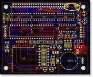
There is a big chance there is a trace gone between J3 and J5. See the picture.

short.jpg
 
Unfortunately, they're still in-tact. That would have been a nice answer, but I just sat and ohmed out most of the power pins, and all look good. I also noticed Ian uses 15ns chips, and the ones I have are 25ns. I think this is the different between 40 & 66mhz, so I can't image this would matter. Just thought I would mention it.

Thanks Hans.
 
@Kevin

The trace I suspect is a ground line and is going beneath the J1 connector. You cannot see the trace.
Have you removed all chips to avoid measurements through chips. For me the speed of the chips is no issue.
 
Hi Hans,

No dice, the ground and power wires are good across the board. Any other thoughts? (Also, I did have two acting up, but only one was ever plugged in backwards.)

Any other thoughts?

Thanks!
-Kevin
 
@Kevin.

The programmer doesn't sound very trustful.
Swap the GAL & PIC from the working FreHD with one of the problem adapters.
Ask somebody in your neighborhood to reprogram these devices, I can do it for you but it is very expensive and time consuming to
send them to Europe and back to the USA.
I think someone in the USA would be so kind to help you. ;)
 
You can send it to me if you like. While the return rate (to help get their FreHD going) for the kit builders has been incredibly low (less than 5), I've always been able to sort them out in less than 1/2 an hour.

Cheers,

Ian.
 
Thanks Ian. I appreciate the offer, but I'll try a few more things before I give up. I was just hoping it was something common, but it sounds like there many be more to this than I first thought.

Anyone have a suggestion for a programmer? Something not too high, but better than all of the $50-$80 multi-burners out on ebay?

Thanks!
-Kevin (TexElec.com)
 
@Kevin

Cheap and good mostly don't go together, but I have used this programmer for the FreHD with good results.
Take a look at this programmer: http://www.ebay.com/itm/USB-MiniPro...d=121767857347&_trksid=p2047675.c100009.m1982

But my best advise is: Let Ian help you, it is the cheapest solution and Ian is the most friendly and helpful guy I know.

If you want to solve the problem by yourself, there is a known problem with the BS170, this is what the manual says about it:
2A. It turns out there are two different polarities for the BS170 (Q1) and the Fairchild product I used for the first 100 or so FreHDs is backwards which is why it is mounted reversed to the screen printing on the PCB. If you are building a FreHD from scratch and it gives flashing RED LED and otherwise won't work, try changing the polarity and see if that helps.
 
Last edited:
Although I have a lot of different programmers and tools, my preferred PIC programmer is the PICkit 2 w/ Sure Electronics ICSP and for Eproms/GALs I use a G540. Both are available for under $100ea. I also use a Ango LA6T Eprom eraser.
 
@Kevin

If you want to solve the problem by yourself, there is a known problem with the BS170, this is what the manual says about it:
2A. It turns out there are two different polarities for the BS170 (Q1) and the Fairchild product I used for the first 100 or so FreHDs is backwards which is why it is mounted reversed to the screen printing on the PCB. If you are building a FreHD from scratch and it gives flashing RED LED and otherwise won't work, try changing the polarity and see if that helps.

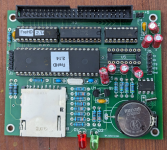
There's another problem with Q1. As wired Q1 doesn't do anything useful. It's supposed to convert the 3.3V data from the SD Card to 5V. The gate of Q1 should be connected to 3V3 without a pullup resistor. Consult NXP Semiconductor's App Note AN10441 for details. You can also remove Q1 & R15 and jumper Q1's Source to Drain. See the attached photo. I did this on my FreHD and it works fine with my 4p. Q1-R15_mod.jpg Hope this helps.

Tom
 
Hello,

Sorry for the long delay. I actually posted awhile back, but I guess I forgot to submit it. I took Hans's advice and bought one of the TL866cs programmers, and my FreHD's now work! Wow, I thought I was losing my mind. I would highly recommend staying away from the VStager units. I think it was programming the PICs incorrectly. Interestingly, the TL866cs complained that the hex file for the FreHD was larger than the memory on the PIC, but it works anyway. Never saw that error on my other programmers. Whatever the case, I can finally move on.

Thanks so much for everyone's help, and sorry for the delay in response. It took awhile for the new programmer to get here.

Take care,
-Kevin
 
I agree that it's probably not needed. Honestly, there are several changes I would propose making to the board, but all in all, they work fine as designed. I think the original version didn't have the FET, so there must have been a reason it was added down the road.

As much as I've used them, I've never seen an error on a read or write.

Thanks Tom, and take care,
-Kevin
 
Hello All:

I can't believe I found this thread!

So I've built my own FreHD for my TRS-80 Model 4, and am having trouble making it work.

So here's my situation. I built it according to the schematics in the 2.14 release (schematics say date of 20-Apr-2013). In these schematics, it says use a PIC18F4610, so I tried that first, and nothing worked. I checked with Fred V. the designer, and he said it needed PIC18F4620, as the 4620 has EEPROM which is needed for the bootloader. So I get the 4620, and program it using firmware 2.13 via a PicKit3.

I test power my FreHD, and it flashes D2 on power-up and also when I plug in an SD. According to my info, this is correct behavior.

I have a TRS-80 Model 4, with U68 showing:

SCM91248P
TANDY c 80
8041364
M 8341

and Ian kindly verified I needed Model 4 NGA Gen1 ROMs for the autoboot ROM in U70. I didn't have any working 2716 EPROMS, so I doubled up the image onto a 2732 EPROM, programmed it with my Stager VS4000, and plugged it in.

So I check my TRS80, and it seems perfectly normal after this ROM replacement. I can boot from a floppy, enter into BASIC, and type in a short program. I can boot into Model III mode and enter a program. I guess this proves the EPROM I burned is okay?

So now I turn off, connect a home-made ribbon cable (with 50-pin card-edge connector to IDC, which I spot checked connectivity and seems good), turn on the FreHD (powered externally), install an SD (formatted FAT32, with frehd.rom, lsdos, ldos3, newdos3d, and cpm files on it, downloaded from Ian's website) and see the D2 LED flash once quickly.

I turn on the TRS80 and it does not boot from the FreHD. I can use the TRS80 normally with the FreHD attached like this, and it's just like before the FreHD was connected. No flashing LEDs or anything on the FreHD during boot.

So now I do a search, and find this thread about the BS170, and sure enough, I've got a Fairchild BS170. Does my scenario sound like the BS170 could be reversed in its polarity? I've wired it up according to the schematics (with the gate and source connected to SD pin 7, and the drain to PIC18F4620-pin 23).

So I'm all about to reverse it, but wanted to check to see which was the best way to resolve this. The way I've wired my board, reversing the BS170 will be a pain, so I wanted some input before I underwent this. I also don't have a spare BS170 if I botch the job up. I guess if the reversal doesn't work, I can try without the BS170 as someone has suggested.

Any suggestions before I give this a shot?

Thanks!
 
Last edited:
So I couldn't stand the wait, and I had some time this afternoon, so I went ahead and rewired my FreHD around the BS170.

Guess what? It works now!

Geez, I can't believe how much time I spent checking and rechecking my wiring - all because a part was manufactured "backwards"! I'm so glad I found this thread. It saved me!
 
Ditto to contacting Ian
Got to meet him personally at Tandy Assembly (photo is Trsbit magazine of the two of us) and he is AMAZING. He WILL get your boards working - GUARANTEED
He has been a Godsend to me for the past few years

Good luck
Jay
 
There's another problem with Q1. As wired Q1 doesn't do anything useful. It's supposed to convert the 3.3V data from the SD Card to 5V. The gate of Q1 should be connected to 3V3 without a pullup resistor. Consult NXP Semiconductor's App Note AN10441 for details. You can also remove Q1 & R15 and jumper Q1's Source to Drain. See the attached photo. I did this on my FreHD and it works fine with my 4p. View attachment 1019686 Hope this helps.

Tom
Hi all, I know this thread is kind of old, not sure if anyone is following it still.

I have done a build exactly as shown in the photo (using this project posted on PCBWay, thanks all!), and have flashed the PIC and GALs. I am in the process of debugging it. I get the momentary green flash when I power up, or when I insert an SD card, so that seems like a good sign.


It turns out though, that PCBWay had installed R15, so I had to remove it. But that got me into studying in depth the eliding of Q1 and R15 from the build.

As I've dug in, I was a little concerned that shorting out Q1 could impact reliable operation. I wanted to share my thinking and get anyone's feedback on it. I would not be at all surprised if I'm missing something.

What I found in my digging was:
  • The SPI_SDI signal is connected to pin RC4.
  • RC4 (and all of port C) have Schmitt trigger inputs (PCI datasheet section 9.3)
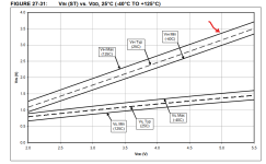
  • VIH for Schmitt trigger inputs is spec'ed as 0.8VDD min (param "D041"), datasheet section 26.3), which is 4V
But the SD card can only bring it up to 3.3V without a pull-up. Thoughts? I read the app note and I see why the decision was made to leave out Q1 - the gate is supposed to be connected directly to 3.3V, not tied to SDI.

I studied the VIH spec in a little more in depth, and it looks like it's likely to typically work at 25C, but could get hairy as temps rise. This is from the PIC datasheet.

1713641917649.png

I guess arguably it's unlikely to be an issue at room temperature, if the SD card is able to pull the signal all the way to the rail.

It sounds like folks have not had any problems with these. But nonetheless, as long as I have the boards in front of me and my soldering iron out, I'm wondering if the "best" approach would be to install R15 and Q1 but peel up the gate lead and haywire it to 3.3V. Thoughts? Am I just making it more complicated than it needs to be? Any reasons to *not* make my haywire mod?

Thanks,
Brad
 
The "proper" way to do the fix is tie the Gate of Q1 to 3.3V so Q1 buffers the SD card from the PIC. The "hack" of removing R15 & Q1 & installing the jumper is certainly simpler. I still haven't modded my FreHD to keep Q1 in the circuit. :)

Tom
 
The "proper" way to do the fix is tie the Gate of Q1 to 3.3V so Q1 buffers the SD card from the PIC. The "hack" of removing R15 & Q1 & installing the jumper is certainly simpler. I still haven't modded my FreHD to keep Q1 in the circuit. :)

Tom
Thanks. I think I'll give that a go then. I'll post back here if I get it working.
 
Thanks. I think I'll give that a go then. I'll post back here if I get it working.
This did indeed work.

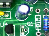
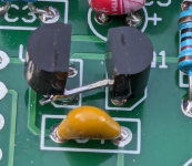
The required fix is quite simple. As shown here, you don't put Q1's gate lead into its hole in the board, but instead run it over the to voltage regulator U4 right next to it and solder to its output leg.

I'll note that
1) This is the OnSemi version of the B170. I've heard that different vendors have different pinouts.
2) This is for PCB rev 3.01 of Fred's design. Since building this, I noticed that there is a later version than this, where Q1 seems to be facing the other way, and I have a hunch that this bug may have been fixed.

But at any rate, it works great on my board and I'm glad I installed it.

1714199808157.png

1714199843513.png
 
Back
Top