• Please review our updated Terms and Rules here

Omnibus Interface Circuit Needed

BitWiz

Experienced Member
Joined
Sep 7, 2021
Messages
423
Location
Glen Ellyn, Iil
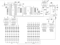
I am not good at hardware design (sorry i'm mainly a software guy). I'm looking for a design/circuit that for inside some kind of programmable logic that would be a bus access interface that would be controlled by a micro (raspberry pi pico in my case). Here are the capabilities I'm looking for:
  1. Read from memory (all fields)
  2. Write to memory (all fields)
  3. Halt the CPU
  4. Restart the CPU
  5. Clear the CPU
  6. Address Load
  7. Extended Address Load
  8. Capture bus frames (to be sent to the pico via high speed spi and DMA on the pico)
  9. 1 cycle data break for both reads and writes.
  10. Address, r/w and data comparators to implement a breakpoint. This would signal the pico that a match happened, issue an omnibus halt. The pico will restart the CPU.
The goal of this is to make a debugger board that using the pico can connect to a serial terminal or a PC and implement the following capabilities. This is similar to the old ROM monitors/debuggers on early 8 bit micros. In theory this could even replace the front panel on systems that don't have one.
  1. Bootloader
  2. Read/Write memory
  3. Set a break point
  4. Clear a breakpoint
  5. Program Trace (via the bus capture capabilities)
  6. IOT handler for I/O device emulation (DF32, RS08, KL8E, RX8E/RX28, RK05, RL8A, etc.)
  7. Memory Disassembly
  8. Simple Assembler into memory
  9. External I2C Octal/Text status display with on the fly code disassembly when examining or single stepping from the front panel.
 
Are you familar with Joerg Hoppe's UniBone (for Unibus systems) and QniBone (for Q-bus systems) projects?
What you're describing seems like something that could be called the OmniBone (for Omnibus systems).

Back in the day... DEC actually made a (very) few KC8-HA and KC8-HB Omnibus options. These were specialty front-panel / debugging aids. I presume they were used for software development. I recall seeing one installed in a DEC field service training lab. It had the KC8-HA (MARS panel) that displays the AC, PC, MA, MD, MQ and status lights) -similar to an PDP-8/I front panel. It also had the KC8-HB which had a small external box with 4 (or 5) octal thumbwheel switches. The operator would set the thumbwheels to an address of interest and the KC8-HB would halt the system when MA = thumbwheel switch value.
 
Last edited:
Back in the day... DEC actually made a (very) few KC8-HA and KC8-HB Omnibus options. These were specialty front-panel / debugging aids. I presume they were used for software development. I recall seeing one installed in a DEC field service training lab. It had the KC8-HA (MARS panel) that displays the AC, PC, MA, MD, MQ and status lights) -similar to an PDP-8/I front panel. It also had the KC8-HB which had a small external box with 4 (or 5) octal thumbwheel switches. The operator would set the thumbwheels to an address of interest and the KC8-HB would halt the system when MA = thumbwheel switch value.

MIT apparently made a similar board for UNIBUS PDP-11s, and called it an MB11. For "Memory Break", though perhaps as a nod to the PDP-8 MARS panel, the device is referred to as a "MAR" in other places. Instead of halting the processor on a specified address, the MB11 triggers an interrupt. The SITS kernel can be assembled with code to support it, which likely means that it played a role in debugging both SITS and LOGO.

I can only find a few oblique references to the MB11, though it is documented nicely here:
https://github.com/larsbrinkhoff/mit-logo-and-sits-raw-files/blob/master/files/3100055/rjl/mbr.14

There's a small diagnostic for the MB11 as well
https://github.com/larsbrinkhoff/mit-logo-and-sits-raw-files/blob/master/files/3100055/rjl/mbtst.34
(Though not having ever seen an MB11, I have no idea if the diagnostic actually works... Lars Brinkhoff and I have found bugs in the source code contained in these old tape dumps!)

It looks like it would be easy to write a Unibone-based driver to emulate an MB11; right now I've stubbed it out...

Michael
 
I have never looked seriously at this idea but I wonder if concepts from the OSI-300 trainer could be transplanted to the Omnibus or Unibus?
The OSI-300 was a minimalist 6502 board with LEDs and switches for data and address paths.
These LEDs and switches were connected to open collectors, omnibus uses open collectors also it seems to me?
The single stepping function used a hardware circuit, IMO it looks like a bus request/grant mechanism.
 

Attachments

  • osi300circuit-1024x775.jpg
    osi300circuit-1024x775.jpg
    159.1 KB · Views: 8
Are you familar with Joerg Hoppe's UniBone (for Unibus systems) and QniBone (for Q-bus systems) projects?
What you're describing seems like something that could be called the OmniBone (for Omnibus systems).

Back in the day... DEC actually made a (very) few KC8-HA and KC8-HB Omnibus options. These were specialty front-panel / debugging aids. I presume they were used for software development. I recall seeing one installed in a DEC field service training lab. It had the KC8-HA (MARS panel) that displays the AC, PC, MA, MD, MQ and status lights) -similar to an PDP-8/I front panel. It also had the KC8-HB which had a small external box with 4 (or 5) octal thumbwheel switches. The operator would set the thumbwheels to an address of interest and the KC8-HB would halt the system when MA = thumbwheel switch value.
I am familiar with the Unibone project and my plans are to do something like that. Eventually linking to Eclipse and some kind of PAL-8 Assembler or C compiler but I need the hardware first and then I can write the monitor/debugger software and then the eclipse stuff later.

Douglas Electronics made a Remote front panel for the 8 back in the day also.

I worked for Gimix on 6800 and 6809 SS-50 bus systems in the early 80's and I want to model the debugger after MIKBug/GMXBug. I also worked for SDS on their 68000 FreeForm debugger (based on the C-Shell). I would like to add some of FreeForm's features as time allows. Like conditional breakpoints.

I have never heard of the KC8-HA and KC8-HB.

Thank you for your feedback.
 
I have never looked seriously at this idea but I wonder if concepts from the OSI-300 trainer could be transplanted to the Omnibus or Unibus?
The OSI-300 was a minimalist 6502 board with LEDs and switches for data and address paths.
These LEDs and switches were connected to open collectors, omnibus uses open collectors also it seems to me?
The single stepping function used a hardware circuit, IMO it looks like a bus request/grant mechanism.
If this was a modern microprocessor i would have no problem designing the interface circuitry. However, the Omnibus as many timing states and modes. I don't fully understand all of it. I learned a lot from Roland's bootloader but that doesn't do reads just writes. If possible, I would like to add DMA to increase read and write speeds when doing memory dumps or loads.

I would like the debugger to have the option of saving a snapshot of memory and this would be faster using DMA. Though, speed it not all that important once the CPU has been stopped.
 
MIT apparently made a similar board for UNIBUS PDP-11s, and called it an MB11. For "Memory Break", though perhaps as a nod to the PDP-8 MARS panel, the device is referred to as a "MAR" in other places. Instead of halting the processor on a specified address, the MB11 triggers an interrupt. The SITS kernel can be assembled with code to support it, which likely means that it played a role in debugging both SITS and LOGO.

I can only find a few oblique references to the MB11, though it is documented nicely here:
https://github.com/larsbrinkhoff/mit-logo-and-sits-raw-files/blob/master/files/3100055/rjl/mbr.14

There's a small diagnostic for the MB11 as well
https://github.com/larsbrinkhoff/mit-logo-and-sits-raw-files/blob/master/files/3100055/rjl/mbtst.34
(Though not having ever seen an MB11, I have no idea if the diagnostic actually works... Lars Brinkhoff and I have found bugs in the source code contained in these old tape dumps!)

It looks like it would be easy to write a Unibone-based driver to emulate an MB11; right now I've stubbed it out...

Michael
Michael,

Good luck on your Unibone project. I don't have a name for this project yet though Omnibone seems to makes sense.

I don't have the time or resources to do both PDP-8 and PDP-11 projects. Considering that my PDP-8/E hasn't even been turned on in months:oops:
 
I did a board that does some of what you wanted a long time ago. Not terribly well documented so not sure how useful. This was for my online pdp-8 which allowed front panel operation remotely and did data break transfers to allow fast reading/writing to devices. Currently the 8/E is not online. Parallel port interface back to controlling computer.
http://www.pdp8online.com/pdp8em/pics/controlboard_back_large.shtml?small
Impressive wiring job.

If I can get something working I would have a PCB made. I work with a local Contract Manufacturer with my company so I'm sure i can get a small quantity of surface mount boards built. The issue is the FPGA circuit and the open collector bus drivers.

Do you have a schematic for your interface? Maybe I can start with that?

Thanks,

Mike
 
I made a Omnibus peripheral emulator from a Microsemi SmartFusion SOM. It has a ARM Cortex-M3 as a hard core in the FPGA. It was an interesting project. The most difficult part was the getting the 3.3V<->5V voltage conversion circuitry to meet the current requirements to drive the backplane.

 
Do you have a schematic for your interface?
Maybe. From CPLD file dates looks like I started it in 1998 so schematic was hand drawn. Its tucked away somewhere safe but I'm not sure where that is right now.
 
I made a Omnibus peripheral emulator from a Microsemi SmartFusion SOM. It has a ARM Cortex-M3 as a hard core in the FPGA. It was an interesting project. The most difficult part was the getting the 3.3V<->5V voltage conversion circuitry to meet the current requirements to drive the backplane.

Very interesting. Did your design implement Data Break? I really like the I/O decode in hardware, that makes the software simpler. I like using the Raspberry Pi Pico and not having to deal with Linux and still have a dual core 133 MHz CPU plus the PIO to handle some of the bit flipping.

Could I possibly get a copy of your schematic and software?

Thank you.
 
Back
Top