• Please review our updated Terms and Rules here

Osborne 1 Screenpac

Gary C

Veteran Member
Joined
May 26, 2018
Messages
2,380
Location
Lancashire, UK
Hi

Does anyone have a screenpac fitted to their OS1 and could take photo's of it ?

I have one but its missing the wiring, and the manual is suitably vague about what connects to what, especially the coax cable fitted from B13 to the screenpac ?
 
Yes, I have those and the fitting instructions but the pictures are very poor and the screenpac has multiple connections to the main board including one which it describes as a coax cable connection, though I suspect that in later versions its not there.

It appears its not just a simple job of pull two chips and push it in, but it should become more apparent when I get the board.
 
Board has turned up but progress has stalled due to repeated faults on the Museums 8032 & 3032 PET's which are needed for display purposes and the boss's plea for an PC/AT to be included into the display which means our rusty unit is now undergoing a full case restoration (hopefully the filler will be set when I get home so I can sand it down and spray it). The rust is so bad that the PSU case has disintegrated and you can get your hand in through the holes !

Even worse, the chiller cabinet got warm and we had to throw some sandwiches away (the controller burnt out so I replaced it, but the instructions had an error. The defrost time was in hours not minutes, so I set it to defrost every 60 hours :( ) so that used up even more time.

Anyway.

It looks like the early unit came with clips for the IC's which must have proved unreliable and so the instructions changed to soldering onto the pins. Mine has soldered pins but has more connections that the manual states but does not have the coax connector. I think mine is an earlier unit and the two ribbon connections for video must have been susceptible to noise.

Bit of a ramble but I want to have this unit on the bench after Easter and give it a go.
 
Its after Easter - Obligatory update requested :)

If it helps, I may have some more information on the Screen Pac in a few weeks - assuming nothing further goes wrong with my latest purchase through the Global Stealing ... er Shipping program. And assuming the photographs are correct.`

Do you see what I see?

I probably shouldn't tempt fate until it's here with me... But below the pic from the item description.

SCREENPAC.JPG
 
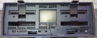
It gets better - Have a look at the ventilation slots just below the monitor and above the keyboard. :) There's only the Screenpac that has the 40 pin socketted chip and the color ribbon cable like that :) Let's hope it matches what you have... Either way, I can document what I find and take pictures
 
I am still working on an 80 column update for the Osborne 1... Which is the main reason for a Screen PAC.

You can get composite adapters that plug into the shunt and take a cable out to a composite monitor. They work pretty good and i use one when testing PCBs on the bench. If you want to make up a PCB to do it, they only have a single chip and a transistor and a few passive components IIRC.

David.
 
But when you pull the shint the crt cuts out. So with this shunt adapter you would only get composite out and no CRT correct?
 
Hmm? No - they both work together and have the same resolution - ie, 52x24.... Though with the screen pac that goes up to 80x24 or more.

But the cheap shunt/composite output does work at the same time as the monitor as it completes the shunt also... The internal monitor of the osborne runs the same as a composite monitor, only the sync looks a bit different and is separated to Horizontal, Vertical and Signal.... The adapter just mixes them up into a single composite signal. You could probably almost do it with just diodes and resistors, except the horizontal signal is a square wave so you need a pulse generator in there somewhere too.
 
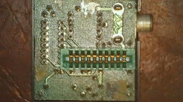
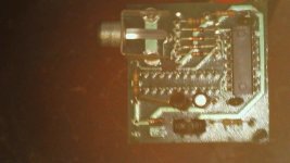
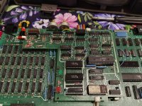
Pictures of mine... 74123N is a retriggerable multivibrator - ie, there is a capacitor and resistor that control the pulse width of the output, which is triggered by either a negative or positive edge of an input signal...

So this generates the horizontal pulse, and there's some transistors to mix up the signals, and a few diodes and resistors. The "transistor" with a heatsink is a 78L05 5v regulator ( 12v is supplied by the edge connector ) and the transistor has the markings 149/ then P N then 2222 which I think is a 1N2222 or a PN2222A small NPN transistor. If you like I can draw out the actual circuit. Though you can probably figure it out from the below. The 10K pot sits on the TOP when installed for orientation of the edge connector, which is not polarised.

iu


WIN_20230507_22_48_29_Pro.jpgWIN_20230507_22_49_21_Pro.jpg
 
That little adaptor came with my otherwise virgin OCC1, so it was on my list to "reproduce" as well.

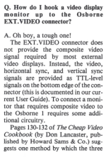
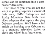
The first edition of "The Portable Companion" (June/July 1982) does mention a simple method of turning it into a composite signal:

Screenshot from 2023-05-07 22-52-29.png

Screenshot from 2023-05-07 22-59-22.png

I've so far not found the article in the other issues, but as David says I imagine it's pretty simple. That said, the shunt I have only seems to work on CRTs so far, since I imagine it's a non-standard signal and the digitisers in LCDs have no idea how to interpret it.
 
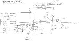
schematic.JPG
Quick sketch of the circuit that I can see - There are two one-shots that take different edges from the sync signals and generate pulses. And there is the diode network that mixes everything up. The two diodes inline for the video signal means that the signal will be about 0.6v p-p above the sync level, so around 1v altogether with a slightly brighter black level. Works OK with digital monitors that I've tried so far. My pot is around 8.3K as an initial setting.
 
Back
Top