shirsch
Veteran Member
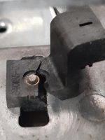
I recall seeing a post somewhere about drilling holes in the posts and fastening them in with small sheet metal screws.
| VCF West | Aug 01 - 02 2025, | CHM, Mountain View, CA |
| VCF Midwest | Sep 13 - 14 2025, | Schaumburg, IL |
| VCF Montreal | Jan 24 - 25, 2026, | RMC Saint Jean, Montreal, Canada |
| VCF SoCal | Feb 14 - 15, 2026, | Hotel Fera, Orange CA |
| VCF Southwest | May 29 - 31, 2026, | Westin Dallas Fort Worth Airport |
| VCF Southeast | June, 2026 | Atlanta, GA |
")
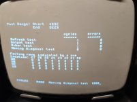
Ah, drive B doesn't work (not tested drive A yet, not sure how to change the drive select yet)

You can boot from the 2nd drive by hitting “ instead of Enter on boot- the second drive becomes A and first is B.