Upcoming Events:
| VCF West | Aug 01 - 02 2025, | CHM, Mountain View, CA |
| VCF Midwest | Sep 13 - 14 2025, | Schaumburg, IL |
| VCF Montreal | Jan 24 - 25, 2026, | RMC Saint Jean, Montreal, Canada |
| VCF SoCal | Feb 14 - 15, 2026, | Hotel Fera, Orange CA |
| VCF Southwest | May 29 - 31, 2026, | Westin Dallas Fort Worth Airport |
| VCF Southeast | June, 2026 | Atlanta, GA |
-
Please review our updated Terms and Rules here
You are using an out of date browser. It may not display this or other websites correctly.
You should upgrade or use an alternative browser.
You should upgrade or use an alternative browser.
Osborne
- Thread starter Gary C
- Start date
Gary C
Veteran Member
Dave, that takes all the fun out of it 
But a good idea, might just get one.
But a good idea, might just get one.
DeltaDon
Veteran Member
deleted
Gary C
Veteran Member
Moving forward. Three failed chips found so far and thats rows 4,3 and 2 now testing fine.
Now I need to check the bank switching is operating correctly before attempting to check row 1.
I think I might refine the testing program to switch rows whenever the reset button is pressed as it works via the NMI input to the Z80 which should enable me to jam a routine in there.
Now I need to check the bank switching is operating correctly before attempting to check row 1.
I think I might refine the testing program to switch rows whenever the reset button is pressed as it works via the NMI input to the Z80 which should enable me to jam a routine in there.
Gary C
Veteran Member
So, code now altered so that it checks Row 2, then when NMI is asserted checks Row 3 then 4, when NMI is pressed again, it copies code into row 2 and jumps to it, bank swaps the EPROM for row 1 of RAM and tests that. Now showing failed chips for bits 1,3 & 5.
Once they are all testing fine, it will be on to testing the video display
Once they are all testing fine, it will be on to testing the video display
Gary C
Veteran Member
So, all the memory tested and 6 chips found to be at fault.
All replaced but still no joy. I have verified the contents of the OS EPROM and that all looks fine, so now I am going to test the video sub system and boy what a design. The video memory is 128x32 lines but only shows 52x24. It has two counter circuits that skip through part of the video memory, the counters being reset by the blanking pulses. A 6821 PIA uses a couple of ports to set the starting position of the counters, thus the memory location it gets the characters for the screen and thus whats displayed.
It does look as if one of the counters is not clocking correctly but I want to test it fully. Might as well write a bit more code to do a full test of the PIA, counters and display as I never know when it might be needed again.
Gary C
Veteran Member
It seems to crash somewhere in the boot rom
Does anyone have the source code for the ROM in a manipulatable Z80 mnemonics ?
The one printed in the manual needs laborious conversion to compile under ASM80, but I think I need something to put breakpoints in to find out which part of the sequence is not working.
I think its in the hardware initialisation routine.
gertk
Experienced Member
Ah well
I am thinking of whipping up a 4116 tester. Have bought a largish batch of chips so I have a bit of stock.
Should be an easy arduino project if it wasn't for the voltages needed, though I could use an old PC supply or repeat the -5 voltage trick from the osborne.
For my homebrew Arduino DRAM tester in order to test 4116 (instead of 4164/41256) I made an adapter board with another ZIF socket and two miniature DC/DC converters to create the -5 and +12V.
Gary C
Veteran Member
In the end, got the device recommended by Dave. Just too cheap and simple to bother messing about.
Gary C
Veteran Member
Boy did they make the video part complicated. The address lines are stepped through using four programmable counters set by a PIA then multiplexed with the CPU access using a couple of clocks. The counters start point can be set by the PIA output lines allowing the screen to hardware scroll about the 128 column, 32 line memory to display the 24 line, 52 column shown on the screen.
Of course using 4116 memories means multiplexed addressing so that adds even more complexity.
So I wrote a program next to write characters to video memory and reset the PIA that is used to select the area of memory that is used to drive the screen and could see that some characters were fine, but others were offset. Quick check and found another RAM chip that had passed my CPU driven memory test but was failing to output anything when driven by the video, ah well. That's 7 RAM chips failed on this unit.
Chip changed and now...........
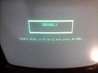
Thats enough though for tonight. When I plugged the keyboard in last time, one resistor on the 12v supply got very hot.
Progress
Of course using 4116 memories means multiplexed addressing so that adds even more complexity.
So I wrote a program next to write characters to video memory and reset the PIA that is used to select the area of memory that is used to drive the screen and could see that some characters were fine, but others were offset. Quick check and found another RAM chip that had passed my CPU driven memory test but was failing to output anything when driven by the video, ah well. That's 7 RAM chips failed on this unit.
Chip changed and now...........

Thats enough though for tonight. When I plugged the keyboard in last time, one resistor on the 12v supply got very hot.
Progress
agentb
Experienced Member
Congrats on getting to the boot screen, great work!
Gary C
Veteran Member
Keyboard now seems to work too. Not sure why the resistor R21 got so hot as while the drawing shows it goes to the keyboard connector and the serial port, the jumper to the keyboard is out so the 12V does not appear on pin 19 and I had nothing in the serial connector. Its possible I might have trapped somthing when putting it together to test.
Enter makes it access drive 1 but not got any disks yet. Will probably put a Gotek in first (with the appropriate wiring mods).
Really happy the screen is so clear and bright with no screen burn. It was probably mainly used with an external monitor which is probably why the video shunt is missing.
In other news, I also bagged an earlier Osborne 1. Thought I might as well put all this learning to use on another none working machine
https://github.com/Gary-Clark/Osborne-1-diagnostics
agentb
Experienced Member
Excellent project here if you are looking to hook up a gotek:
https://github.com/WayneVisser/Osborne1FloppyAdapter
https://github.com/WayneVisser/Osborne1FloppyAdapter
Gary C
Veteran Member
Cheers.
I will have a look at that.
A gotek without the top fitted, slides nicely into the storage slot (al a comm pac) below the floppy drive and with a bit of double sided sticky tape I should be able to have a gotek without having to do any case modifications at all and retain the look of the unit (on the later blue case, the storage slots are vented and I should be able to feed a folded ribbon cable through). I might even put a switch to select the Gotek or drive A.
On the replacement video shunt, I have made one up but its smaller than an original (as I have also obtained a second, earlier Osborne 1 with the shunt), the original part that Osborne used was a TD6720BRN and there are a very few placed that have some in stock, but they all seem to be in the US
https://www.electronicsurplus.com/midland-ross-td6720brn-ribbon-cable-to-20-pin-edge-card-connector
Unfortunately, the shipping to the UK is daft. Will have to keep an eye out.
Gary C
Veteran Member
Damn
Osborne number 2 is all fixed up but its keyboard is showing a short between two rows and one column.
Keyboard out and the problem is somewhere in the membrane. All keys removed by melting and cutting the mountings and the membrane has been removed, and now the short has cleared but not all the keys seem to work.
I have read that someone has actually and successfully separated the layers of the membrane, cleaned them and reassembled it so it looks as if I have a long road of carefully working on this unit
Gary C
Veteran Member
Update
So all the keys of Osborne number 2 removed. They originally, the mounting stalks are melted into place and need melting back out again
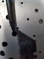
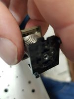
The keys then pop out, but the springs look easy too lose.
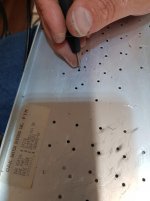
And once peeled from the plate, the membrane is now out.
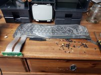
Made up a test lead, and, yep, several shorts between rows and columns. The membrane is a bit twisted, so using the rework torch to heat it up, I have smoothed it all down and now the shorts have vanished and all the keypads seem to work.
Connected to the machine, the constant keypress has gone, and most of the pads appear to respond but I think I now need to boot a machine and test the keyboard in its entirety.
Not sure how I am going to get the keyswitches reinstalled though. At the very worst case, I will have to make up a new PCB using cherry MX keys and try to fit the original keycaps on to them, but fingers crossed.
I now need to get the machine to boot. I have a Gotek and I have just received some of Waynes PCB's that I have had made up (how to jcl do it so cheaply). I intend to install a Gotek in the newer machine and have this older machine running floppies, but first as its the one on the bench, I am going to get this one running.
Seem to have run out of 34 way connectors though, so will have to wait for a few days now.
So all the keys of Osborne number 2 removed. They originally, the mounting stalks are melted into place and need melting back out again

The keys then pop out, but the springs look easy too lose.


And once peeled from the plate, the membrane is now out.

Made up a test lead, and, yep, several shorts between rows and columns. The membrane is a bit twisted, so using the rework torch to heat it up, I have smoothed it all down and now the shorts have vanished and all the keypads seem to work.
Connected to the machine, the constant keypress has gone, and most of the pads appear to respond but I think I now need to boot a machine and test the keyboard in its entirety.
Not sure how I am going to get the keyswitches reinstalled though. At the very worst case, I will have to make up a new PCB using cherry MX keys and try to fit the original keycaps on to them, but fingers crossed.
I now need to get the machine to boot. I have a Gotek and I have just received some of Waynes PCB's that I have had made up (how to jcl do it so cheaply). I intend to install a Gotek in the newer machine and have this older machine running floppies, but first as its the one on the bench, I am going to get this one running.
Seem to have run out of 34 way connectors though, so will have to wait for a few days now.
Last edited:
Gary C
Veteran Member
Anyone help with Gotek compatable software ?
I have the Teledisk images from retroarchive which I then turn into hfe with the HcX utility which seems to give me the right image but it doesn't load. The gotek with flash floppy counts up to track 2 or 3 and hangs.
Might be a problem with the machine of course, but does anyone have a working image and config files for a Gotek working under flashfloppy ?
Gary C
Veteran Member
Ah ha !
Just installed my RAM tester EPROM and I am showing a couple of RAM chip failures in the range $0000 to $3FFF
Now, this is where the EPROM sits but as this is where CP/M also loads system buffers it might be failing I wonder ?
Probably the best thing is to swap out the faulty chips first but any Flashfloppy specific configs would be welcome
shirsch
Veteran Member
Can you explain a bit about the use of a hot-air tool to straighten out the membrane assembly? What temperature, flow rate and distance were used? I have keyboard I'd like to work on, but would rather not melt it into a puddle.
Gary C
Veteran Member
Can you explain a bit about the use of a hot-air tool to straighten out the membrane assembly? What temperature, flow rate and distance were used? I have keyboard I'd like to work on, but would rather not melt it into a puddle.
I have an SMD rework tool and running it at 160C and ran it over the membrane, oddly I could see the pads sort of 'pop up' as it warmed. I started on the corner where there is no tracks and pads to get a feel of how hot I could take it, but really I just made it go a bit 'plastic'
Not reassembled it yet though and that might be a problem as you have to cut all the switches off and they will need to be glued back on somehow.
