| VCF West | Aug 01 - 02 2025, | CHM, Mountain View, CA |
| VCF Midwest | Sep 13 - 14 2025, | Schaumburg, IL |
| VCF Montreal | Jan 24 - 25, 2026, | RMC Saint Jean, Montreal, Canada |
| VCF SoCal | Feb 14 - 15, 2026, | Hotel Fera, Orange CA |
| VCF Southwest | May 29 - 31, 2026, | Westin Dallas Fort Worth Airport |
| VCF Southeast | June, 2026 | Atlanta, GA |
-
Please review our updated Terms and Rules here
- Forums
- Companies
- IBM Computers, PCs, Clones and Descendants
- PCs and Clones (XT and early AT class machines)
You are using an out of date browser. It may not display this or other websites correctly.
You should upgrade or use an alternative browser.
You should upgrade or use an alternative browser.
Paradise PVC2 questions on Olivetti M19
- Thread starter Zare
- Start date

1ST1
Veteran Member
That Commodore circuit diagram is really interesting. So also the PC-1 has monochrome CGA output with single video signal plus intensity. And it has Composite video, mixing of the signal is much simpler than I expected. Also ETV 3000 has composite video to support the ETV 2700 monitor, this M19 based board is abit different because of this.
PC-1 and M19 look like technical brothers.
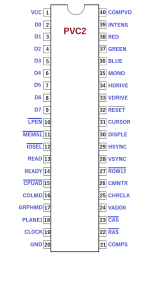
Have you seen, PC-1 has lightpen input on PVC2 (pin 10), if M19 can do as well?
PC-1 and M19 look like technical brothers.
Have you seen, PC-1 has lightpen input on PVC2 (pin 10), if M19 can do as well?
Have you seen, PC-1 has lightpen input on PVC2 (pin 10), if M19 can do as well?
Yes, this pin is routed, to resistor "RLP" in the resistor row next to the U225.
Very curious finding.
That Commodore circuit diagram is really interesting. So also the PC-1 has monochrome CGA output with single video signal plus intensity. And it has Composite video, mixing of the signal is much simpler than I expected. Also ETV 3000 has composite video to support the ETV 2700 monitor, this M19 based board is abit different because of this.
PC-1 and M19 look like technical brothers.
The PAL logic is bit differently laid out, but this should be a very close reference indeed.
COMPS/COMPVD are not connected on the M19 dip socket. Tap out these two wires + resistor array, could this enable composite out?
What could be also possible is Hercules mode, but it would require putting additional 16MHz oscillator instead of bus OSC input, switching the RAM chips for twice bigger, and finding out how to program PVC2...
I've just made a discovery, channel D1, is ZD, I'm channel D4 is I1D.
The Vsync frequency is not stable, that on the left side, I have 60Hz, but on the left side, I have only 30Hz.
This is when I1D sends nothing. Part of the signal is missing, and this happens periodically.
Now we just have to find out where it's coming from.
On schematic it looks like a bit from the address bus.
0:3 should mean first 4 address bits are latched, and the bit 3 goes to I1D. I don't know what other numbers mean...
If we follow PC-1 schema we can see the proper way of disconnecting the onboard graphics card - keep the RST branch between vidgen,CRTC and a PAL at high state.
The BRESET from chipset and NOVID line are being added up and sent to PVC2 RESET, 6845 RST and one PALs input.
If the jumper is set to disconnect the graphics card, SW4 = ON, that puts +5VDC into the NOVID line, keeping the graphics card in reset state.
So there is no such line on M19 but nevertheless the PALs,vidgen and crtc need to receive a reset signal. The resets of PVC2 and 6845 are interconnected but there is no direct connection to PALs.
Finding out how to keep them in reset state is a way to disconnect the onboard M19 card properly without damage.
So after a few years and 25+ pages this sort of answers the original question of the thread - how to get rid of onboard graphics, since there is no jumper to disconnect it...
@Jan de Lange can you probe the composite video and sync pins on PVC2 chip, see if they deliver anything.
If they do, piggybacking couple of wires to a PVC2 socket and terminating to the empty PSOUND hole, then a simple sync/video combiner circuit (resistor network) between M19 and television. Should be an easy TV out mod.
If they do, piggybacking couple of wires to a PVC2 socket and terminating to the empty PSOUND hole, then a simple sync/video combiner circuit (resistor network) between M19 and television. Should be an easy TV out mod.
Attachments
Ghislain
Experienced Member
- Joined
- Jun 1, 2024
- Messages
- 141
I got in touch with a guy who has a youtube channel, and who talks about the M19. He's going to put me in touch with a former Olivetti employee.
He explained to me that it's dangerous to put a graphics card in, otherwise the onboard card will be damaged.
The native card cannot be deactivated.
I think I was lucky.
He explained to me that it's dangerous to put a graphics card in, otherwise the onboard card will be damaged.
The native card cannot be deactivated.
I think I was lucky.
I documented it on around page 2/3 of this thread
If you remove one of the PLs, PVC2 and char ROM, the onboard graphics is going to lay off all the I/O, and the external graphics card is going to function properly. I've done hours on M19+VGA in this way, and tested all VGA functionality working.
Prior to removing the chips, the VGA would work simultaneously with onboard, machine providing two outputs. Basic text mode worked fine, but touching regs either by more elaborate text programs like NC, or going into graphics, froze the system.
Therefore without keeping the PL, PVC2 and 6845 under reset all the time, you cannot disconnect the onboard.
What is done with my workaround, PL is removed and PVC2 is removed, but 6845 isn't. Removing the character ROM seems to bug 6845 enough to not work properly in addressing, but it, and possibly other stuff, can be damaged, maybe due to mandatory load being disconnected.
I believe you haven't tested the graphics outside of the boot screen - don't. Maybe the collision when the system frozes hurts the onboard card.
There is a lot of merit in keeping the external graphics disconnected, supplying an alternate output if it goes wrong for one...we should find a way how to do it properly.
By the way, the GO380 adapter of M24 cannot be removed either, it serves as a bus master.
To put other graphics card in M24 one must switch the PL chips on the GO380 with replacements from Olivetti specially made for this purpose. There are comments on the internet that replacements were just bypass wires in a DIL housing.
There could be a way to replace PL(s) in M19 with static wiring to keep the onboard graphics off.
But the easiest way would be just to solder a socket for CRTC.
With PL1D, CRTC, ROM, and PVC2 out of the system, there are no more chips left that will latch on CGA addressable bus I/O.
On the other hand, with memory-controlling PL out, but CRTC still connected to data bus, it can consume register programming (which can be targeted for non-compatible VGA 3D5 register) but memory refresh lines are open, there is no load. I think this might break it.
I will resocket my VGA-moded board and try a 6845 replacement chip in there, see if the onboard will run. If it does, then it's the most handy solution.
with an external power supply.
If you don't intend to run FDDs and HDDs but from a CF card, you can power up the board using the power out cable and its 5'25" molex socket. There are no diodes between 4 pin power out socket and 8 pin power in socket.
The easiest and most non intrusive alt.power supply, if you don't intend to go for full solution and get that 3x3 pin box Molex (which I haven't found easily orderable), is to just route out a 5'25" molex jack through the ISA expansion bracket, and connect picoPSU from the outside.
choas75
Experienced Member
Hi Jan,Today I upgraded my M19 with a real time Clock (RTC).
Install was painless after I was pointed to the proper driver to be included in the CONFIG.SYS file. The card is so small, it almost seems to be designed with the M19 in mind.
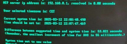
I did the same but since I also use NTP when booting I found out that the RTC is not very accurate. Does yours behave the same?
The picture is taken after not having booted it up for about a week.
Attachments
choas75
Experienced Member
I mounted it in the extension box I got when I purchased the M19 with color monitor. The second one has a solid mainboard so I combined the two.Hey @choas75 how did you connect network card to M19? Do you have a loprofile one?
Mine is hanging downward from Prodest extender...
It's the 8 bit ne2000 card from Tindie.
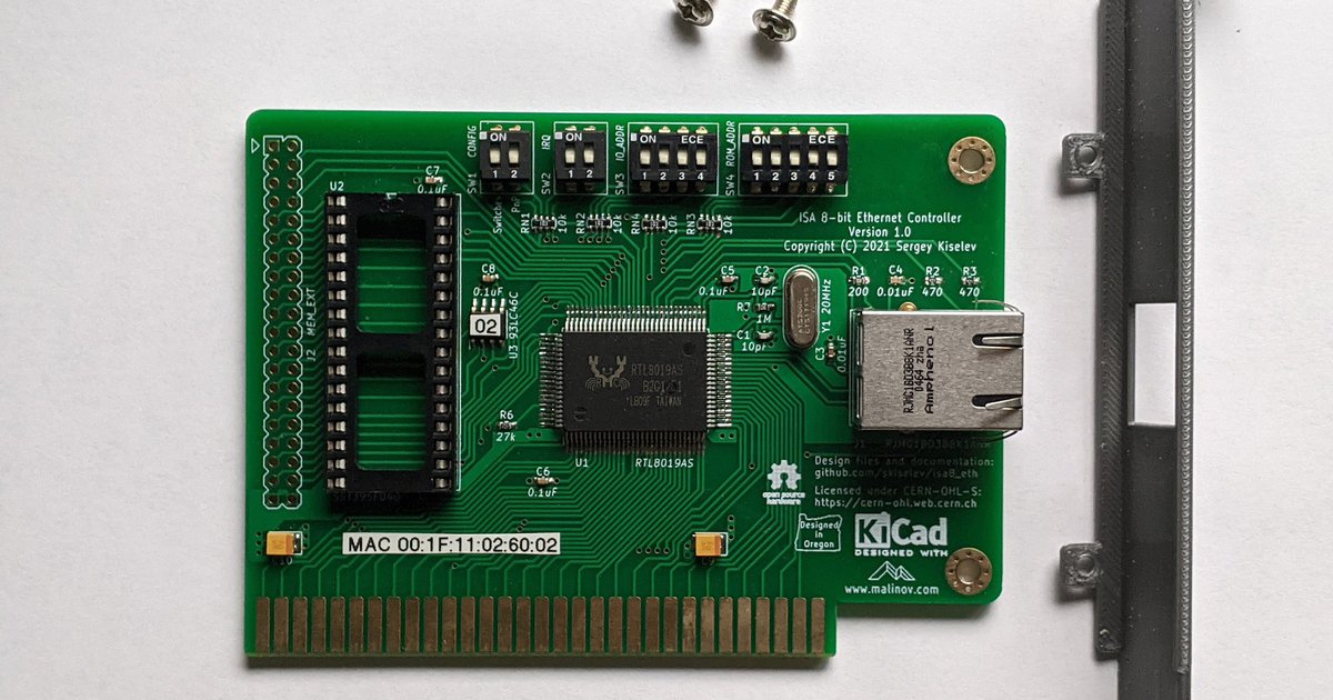
ISA 8-bit Ethernet Controller by Weird Electronics on Tindie
ISA 8-bit Ethernet Controller can be installed in IBM PC/XT and compatible computers to add Ethernet network connectivity
 www.tindie.com
Ghislain
Experienced Member
- Joined
- Jun 1, 2024
- Messages
- 141
Forum broke the link, can you just name the item so I can search for it?
I mounted it in the extension box I got when I purchased the M19 with color monitor. The second one has a solid mainboard so I combined the two.
So you have both expansion boxes, with and without ISA? Wow.
choas75
Experienced Member
Forum broke the link, can you just name the item so I can search for it?