• Please review our updated Terms and Rules here

PDP-11/04 & 11/34 - Testing the M7847 Memory Boards

intabits

Experienced Member
Joined
Jan 22, 2019
Messages
148
Location
Melbourne, Australia
I've made a lot (too many?) of videos about my PDP11/04 and 11/34 computers, but have not yet got past messing with the power supplies and the console interface.

So it's high time to start moving towards running systems by getting more parts of them running. The next logical step is the memory system, and for these computers, that's three M7847 16KW boards. (2 from the 11/04, 1 from the 11/34)

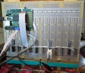
One of the boards:-

usppPEh.jpg


My initial testing shows that one board looks to be operational, one definitely not, and one (literally) half working. The failed one may be as simple as dodgy address selection DIP switches. The half working unit appears to have a stuck bit in the upper 8KW. And as per usual, I manage to get myself confused, and even for the "working" board I need to do some further research and testing.

To help with the testing, I used what I call the "interceptor" module that allows a PC to drive the PDP console. Although working reasonably well, this is still under development, and that may have contributed some ambiguity to the results. But it certainly holds promise as a tool for future automated testing and operation of these computers.

The available engineering drawings are poor quality, such that part numbers are not discernible in the layout drawings, and not much better in the schematics. Together with the lack of part identification on the board itself, this will make working on these boards difficult.


Video of my blundering about:-


https://www.youtube.com/watch?v=yBDXtBa-s-M
 
I thought I had set the video to "publish", but obviously not - it was still private. Now fixed.

Someone commented in the video about even byte addresses (for words) being used on the console. Not having much experience with these machines I was not conscious of that (though it does ring a bell), so my test of the board with a starting address other than 00000, was incorrect, resulting in some confusion.
The second board in the PDP11/04 follows contiguously after the first 16KW board, and I was sending the start address of 16384 (for words), but it should have been 32768 (for bytes). That would be 100000 octal, which is what was working in the earlier section when it was being tested manually.
 
Hi there from a person also in Melbourne Australia.

Question I have is what are you using as the video recorder for you videos?

And how is it mounted to record as you move around please?
 
It's a Nikon P900. I have it on a tripod, standing on the floor next to me.
I don't move it much, but just lift and move/tilt the whole tripod when I do.
 
Continuing with the testing of M7847 16KW memory boards for my PDP-11s, there's been a number of developments:-
- Firmware code for simulating console key-presses, is now more tightly synchronized to the
multiplex scanning of the keypad and display, allowing a significantly faster keystroke rate.
- This may have contributed to the lower occurrence of "Bus Errors".
- More M7847 memory boards found in the dungeon,
- Plus terminator cards, and other useful stuff.
- Good quality print sets for the M7847 engineering drawings
(The only ones available online were too poor quality to be of much use)
- A proper scripting language has been developed for driving the PDP-11 console under control of a PC.
- I now have 5 (maybe 6) M7847 boards that pass the basic test.

Video of these activities:-
https://www.youtube.com/watch?v=2L-Cff57Xk8

For those that may be interested, here is the script used for the memory testing:-
https://pastebin.com/NgMuD4DG
 
I love your videos! Please keep posting. I too have an 11/34 and an 11/04, but have far less knowledge about them, especially at such a low level hardware-wise. Your videos are very educational for me.
 
Could you make a script that uses the serial console of an 11/44 to do the same low level testing that you did by hacking the 11/34 console?
I imagine that it would be much slower than your 11/34 console modification.
 
Could you make a script that uses the serial console of an 11/44 to do the same low level testing that you did by hacking the 11/34 console?
I imagine that it would be much slower than your 11/34 console modification.

As pointed out above, PDP11GUI is probably the go for driving things via a serial interface.

I haven't looked at it yet, since I'm pretty sure that it would have a minimum requirement of both an operational CPU, plus of course the working serial/async board. And again, not knowing for sure, I expect that it would also require an M9301 or M9312 board with the console emulation routines in ROM to get access to memory and gain control of the CPU. Of course once that's all in place, it's off to races, and almost anything can be done.

But the idea behind my interceptor console modification is to get control of the system via a PC program, when the three items mentioned above are not all in place and operational. Oh, and for April Fool's jokes.

And it has access to all the keys on the console (the emulation routines in ROM can simulate only the essential subset of those). So it can start/stop the CPU, single step it, or even put it into maintenance mode and single step through an instruction's microcode.

My next move could be to test any of those items (CPU, Async or M93xx) separately and standalone, using just the console, and/or more extensively with my interceptor modification. I think I'll be jumping straight to testing the CPU next.

So to answer your question, PDP11GUI seems designed to do just that. Or any other PC based program could be writen to provide similar functionality. (I will probably extend my PC program to optionally connect to the Async board, thus allowing its scripts to drive the system via that as well)

Speed wise, nothing could be slower than my console modification. Its maximum possible throughput is about 10 or 11 keypad operations per second, and a number of keystrokes will be required to accomplish anything useful. Contrast that with being able to send 960 characters/second over the serial link, and then after downloading a program, testing can proceed at CPU speeds.
 
The problem that many people have when bringing up a PDP-11 for the first time is that everything is an unknown, and they don't have another PDP-11 to test the boards. Using your console modification would let you test the individual boards before you tried to get them to work as a system. Once you have working CPU, serial port, and boot/terminator boards you could switch to the PDP11GUI.

I am repairing three PDP-8/a programmer's consoles. They look just like the PDP-11/34 console. I imagine that your modification would also work for the 8/a and would allow you to do the same basic tests.
 
...Speed wise, nothing could be slower than my console modification...
Except manual keying of course (and tedious). That's why it was made.

The problem that many people have when bringing up a PDP-11 for the first time is that everything is an unknown, and they don't have another PDP-11 to test the boards. Using your console modification would let you test the individual boards before you tried to get them to work as a system. Once you have working CPU, serial port, and boot/terminator boards you could switch to the PDP11GUI.
Yes, if the complete system doesn't work, where do you start?
The testing that my mod enables could always be done manually, but that gets old quickly, so automation becomes attractive.

I am repairing three PDP-8/a programmer's consoles. They look just like the PDP-11/34 console. I imagine that your modification would also work for the 8/a and would allow you to do the same basic tests.
I have an 8/a also, but the console similarity is superficial only. I just took a look at it and internally they are nothing alike:-
8/a has two displays (they added the address display that I wish the 11s had), and there are more status LEDs.
The 8/a console has 2 PCBs stacked above each other, the 11s have only one.
The 8/a has two 34pin ribbon cables from the console to the innards, the 11 has just one 20 way cable.
I don't know where the cables go inside the 8/a, but it won't be to an M7859 board as in the 11s.
So there's no way my mod would work on an 8/a without a major redesign, but I'm sure a similar thing could be done with some effort. I suspect it will be quite different though.
When I get around to my 8/a, I might give it a go...

.
 
I have an 8/a also, but the console similarity is superficial only. I just took a look at it and internally they are nothing alike:-
8/a has two displays (they added the address display that I wish the 11s had), and there are more status LEDs.
The 8/a console has 2 PCBs stacked above each other, the 11s have only one.
The 8/a has two 34pin ribbon cables from the console to the innards, the 11 has just one 20 way cable.
I don't know where the cables go inside the 8/a, but it won't be to an M7859 board as in the 11s.
So there's no way my mod would work on an 8/a without a major redesign, but I'm sure a similar thing could be done with some effort. I suspect it will be quite different though.
When I get around to my 8/a, I might give it a go...

Connect in parallel to the keypad contacts with open-collector drivers?
 
Connect in parallel to the keypad contacts with open-collector drivers?

I haven't looked at the 8/a schematics, and how it's all done there. But if the keypad and display are implemented in a similar way to the 11/04 and 11/34, then OC drivers to ground would work, because the keys each are grounded on one side. If you mean 20 drivers (one per key) that is.

But what if the keys are in the more common matrix format, with a key at each intersection? Then you have to do it by interfacing with the 4 row outputs. And on the 11s, that couldn't be done with OC drivers, because the signals are are active high. In fact, those 4 row scan lines are the only ones that my "Interceptor" actually intercepts, all other signals could be monitored or driven in parallel with the existing electronics.

And when interfacing with the row signals, you have to activate your simulated keypresses in sync with the column scanning.
But you also need to monitor the displays, so that means reading and syncing with the digit and column multiplex signals anyway.

And then there's the extra status LEDs and Address digits, how they fit into the multiplexing scheme has to be sussed out.
The extra stuff may blow the I/O budget - I had to use all available I/O pins on the Arduino. So I think it's a major redesign.
 
And then there's the extra status LEDs and Address digits, how they fit into the multiplexing scheme has to be sussed out.
The extra stuff may blow the I/O budget - I had to use all available I/O pins on the Arduino. So I think it's a major redesign.

The displayed values are stored in a 4-digit FIFO, so 4x 3-bit values for the data display, 4x 3-bits for the address, 1x 3-bits for the extended address, 1x 4-bits for the LEDs.
Sounds like a lot of I/O and a lot of work.

Maybe making an Omni-Bone would be a better idea.
 
Maybe making an Omni-Bone would be a better idea.

The problem is that the Omnibus has so many singnals. 96 in total. Several parallell buses to convey data and addresses. Unibus has much fewer signals. And the beaglebone have 65 GPIO.

I think the simple Microchip portexpander is a good choice. Connected to an Atmel or STM32Fxx chip.
But it depends a bit what the objective is. An IO board, then it mhght be too slow. But as an system exerciser or remote front panel I think they would work fine.
 
Last edited:
I could restart my Omnibus Peripheral Emulator project. I believe that the FPGA has enough unused I/O to do data-break, so with a little work it could emulate a CPU and then test any I/O board.

Omnibus_PE-1.jpg
 
I could restart my Omnibus Peripheral Emulator project. I believe that the FPGA has enough unused I/O to do data-break, so with a little work it could emulate a CPU and then test any I/O board.

View attachment 60804

Yes. Very much possible. But you need to pull out the existing CPU since they would compete for certain signals. You probably need to make it mimic the IOP pulsen and state very closely in the FPGA.

And then you need to write all those test vectors. A quite daunting task. The DEC Maindec people was really good at testing most corners.

I think I mostly want a way of automating testrunning. Upload diagnostic, set up various bits in SR and memory locations and then make it run. An extended extended M847 board that could load the SR would then be needed. Reading memory locations would be useful as well. Reading back the MA would be nice if it halts.
 
Back
Top