• Please review our updated Terms and Rules here

PDP-11/35 at the RICM

m_thompson

Veteran Member
Joined
Jul 8, 2014
Messages
1,998
Location
Rhode Island, USA
The RICM moved the Display/Lab area into a new rental area that is 50% bigger, so we had room for some more DEC equipment. Last year the estate of Spider Boardman, a PDP-10 operating system wizard, donated an 11/35 that was cobbled together from lots of unrelated parts. I thought that machine might be an interesting project, mostly because it had a VT11 board set in it and a VR14 display. My plan is to use a real 11/35 chassis that we have for the processor, because the current BA-11 Unibus chassis doesn't have any provisions for mounting a front panel.

This should be enough hardware to run Lunar Lander from a GT40. I might try modifying the source code to use the LK11 Button Box instead of the light pen on the VR14 to control the lander.

This system should also be able to run UNIX V2.9 if we add some RK05 or RL02 disks. I think RL02 drives would be less problematic.

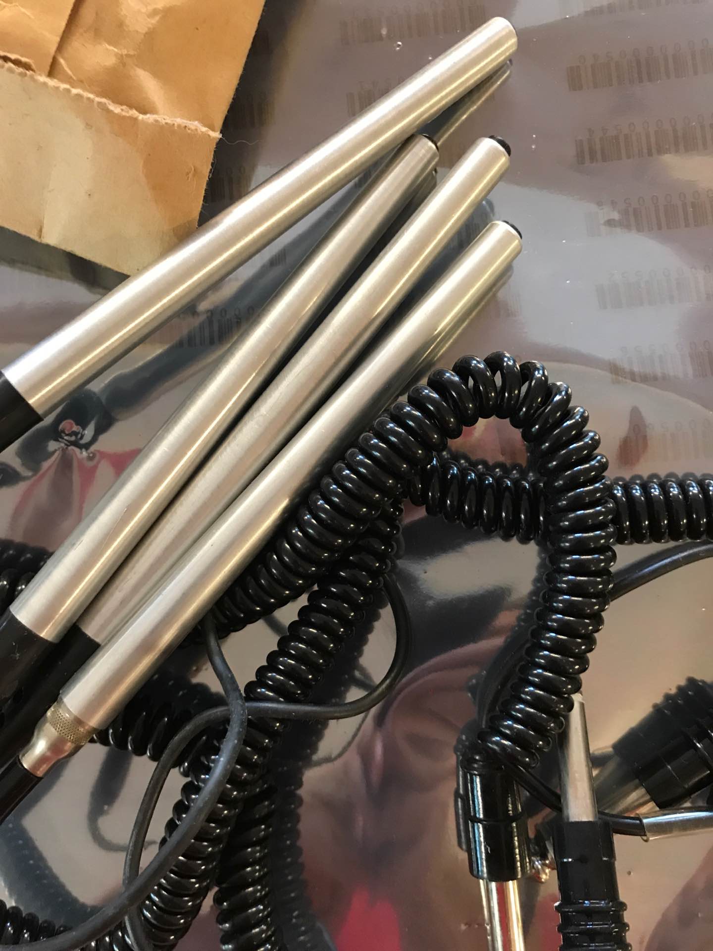
Pictures of the machine are here: https://www.ricomputermuseum.org/collections-gallery/equipment/dec-pdp-1135-2
Comments and suggestions are welcome.

The installed boards are:
  1. M7239 KE11-F FIS Option
  2. M7238 KE11-E EIS Option
  3. M7232 KD11-A U Word
M7237 KJ11-A Stack Limit
M787 Kw11-l Line Time Clock
  1. M7231 KD11-A Data Path
  2. M7233 KD11-A IR Decode
  3. M7235 KD11-A Status
  4. M7234 KD11-A Timing
  5. M7236 KT11-D Memory Management Option
  6. M981 Unibus Jumper
M7800 DL11 Asynchronous Line Interface Board
  1. M981 Unibus Jumper
M7228 KW11-P Programmable real-time clock
  1. M7891-DC MS11-LD 128kW X 18 bits (256KB) MOS Memory
  2. M7800 DL11 Asynchronous Line Interface Board
  3. M7060 LK10 VT48 push button control for the LK11 Button Box
  4. M7860 DR11-C M786+M105+M7821; general device interface
  5. M8256 RX211 RX02 floppy disk drive controller
  6. M9202 Unibus Jumper
M8730 KW11-C Calendar and clock module
  1. M9202 Unibus Jumper
M9312 Bootstrap/Terminator DY, RL02, and ASR33/PC05 boot ROMs
  1. M7014 VT11 Unibus Controller and Bootstrap for VT40
  2. A320 VT11 Vector and Character generators, and D-A convertors
  3. M7013 VT11 Vector Generator and Character Generator Control for VT40
 
391193B7-C068-4555-BAC6-76D0A7BDDB17.jpg
When you have it up and running I can supply you with a light pen.
 
We removed the BA11-KA Unibus chassis from the cabinet and replaced it with a PDP-11/35 chassis. The 11/35 had a 4 slot Unibus expansion backplane. Our plan was to remove the 9 slot Unibus backplane and 4 slot VT-11 backplane from the BA11-KA chassis and install them into the PDP-11/35. Unfortunately the BA11-KA chassis has big Molex power connectors like an 11/44 chassis and the 11/35 has smaller Molex power connectors. It would be a bit of work to make new power harnesses for the 9 slot Unibus and VT-11 backplanes.

Our current plan is to look at the mongrel PDP-11/40 chassis in the warehouse that has a PDP-11/23 backplane in it. Depending on the power connectors in the chassis we will borrow the processor and Unibus backplanes from either the BA11 or the 11/35 chassis. The 11/35 is full now, which will not leave room for storage controllers that we plan to add. The 11/40 chassis should provide lots of expansion room.
 
I looked at the PDP-11/40 in the warehouse. It has the same small 9-pin Molex power connectors as the PDP-11/35. It does have a 9-slot Unibus backplane with the same power connectors as the PDP-11/35. It also has a 4-slot Unibus backplane. We could borrow the power harness from the 4-slot backplane and use it with the VT-11 backplane in the PDP-11/35 chassis.

My plan now is to use the PDP-11/35 chassis. If we need more Unibus slots we can swap the PDP-11/35 chassis for the PDP-11/40.
 
I am curious as to which PDP-11/35 chassis you have. One PDP-11/35 I am well acquainted with came in a BA11-D mounting box where the power supply is found at the rear (similar to the BA11-K), but I have seen two other examples in a chassis that had the power supply mounted along the side instead. I have never seen any documentation of this variant and have wondered for some time if these may have been special builds for a particular market or customer.
 
Well, I'm unable to view that image, but I find this very interesting. Maybe what I thought was the typical chassis is actually the exception.
 
I am curious as to which PDP-11/35 chassis you have. One PDP-11/35 I am well acquainted with came in a BA11-D mounting box where the power supply is found at the rear (similar to the BA11-K), but I have seen two other examples in a chassis that had the power supply mounted along the side instead. I have never seen any documentation of this variant and have wondered for some time if these may have been special builds for a particular market or customer.

BA11-D has the power supply to the right if you stand in front of it. Not in the rear like the BA11-K. The older PDP-11/05 in 10.5 inch chassis also used a BA11-D.
 
We did some research on the MF11-L 9-slot Unibus backplane that we removed from the mongrel PDP-11/40 and had planned to use in the 11/35. Apparently this backplane is for core memory and is not a generic Unibus backplane. Maybe we can use the power harness from this backplane on the 9-slot that is in the BA11 chassis?

We powered on the 11/35 chassis. No lights and no response to switches. We measured the voltages on the backplane power connectors. -15V is on all connectors. +5V is on the left 4 connectors, but not on the two connectors for the processor backplane. Looks like we need to disassemble and repair the power supply. It looks like there is an H740 power supply inside of the H750. This is the same power supply that is in the Omnibus expansion chassis in the PDP-12. We are very familiar with this power supply and have an LTSpice model for it.

One of the DEC docs says that the larger 11/05 chassis uses the same power supply. I believe that there is one on the RICM warehouse. Maybe that H750 works better?
 
Last edited:
Back
Top