• Please review our updated Terms and Rules here

PDP-11/44 Restoration

My multimeter is a Cen-Tech 11 function multimeter with audiable continuity. I also have another one that I don't use much. It is a table top multimeter with similar functionality and is probably of a higher quality (I forget the brand and model).

The spare parts/junk box is virtually non-existent. I only have a few resistors and small capacitors around right now. There is a local surplus store that I can go to get common and obscure parts if I need them.
 
Some good functions. You'll be happy to hear it's designed around a chip, the ICL-7106, which is real vintage. I wanna say it was introduced in '76, but it was definitely around the '80's.
patscc
 
That's pretty awesome. I was expecting it to be based on one of the epoxy blob type chips.

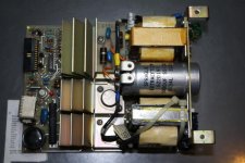
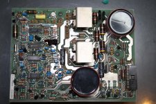
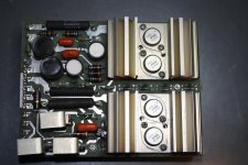
By the way I have taken some pictures of the PSU while it is still all together. I should get them posted later today.
 
Last edited:
I'm still working on removing the output assembly, but after reading the technical manual some more, I think that the problem is probably isolated to the output assembly and/or the Logic inverter and regulator boards (see page 51). I agree that it is not an over temperature situation because the thermal shutdown lines do not appear to be related to any assembly that has to do with the +5v bus (although I could be mistaken because the diagrams are a bit complex).

I also think that the problem is not related to the power distribution board because the +5v bus does not connect to that. I think that it is safe to say that the Bias and Interface board is sound for two reasons. The first reason is that the relay in the input module activates after a second or two. Based on my understanding of the manual, that board activates the relay. The second reason is that the PSU fired up again after a few minutes. If something was bad on that board then I don't think that the PSU could fire up (plus the replaced capacitors still appear cosmetically fine). Another possibility that could be ruled out is that C1, C2, or C3 are shorted (they could still be bad though) because if the +5v was shorted to ground, much worse things probably would have happened.

What do you think about these ideas?

I forgot to mention, I can't find the air flow sensor in the technical manual, and the print set does not seem to have it either.
 
Last edited:
The whole PSU is normally cooled by a fan assembly, isn't it ? Was that on ?
I'll think on it, and try to grok the service manual tonight or tomorrow.
patscc
 
The fan assembly is still in the mounting box. Do you think that not having it conected could cause something?
 
I think all the heatsinks are probably spec'd to operate with forced air cooling, rather than passive, which is why things might be getting too hot. Do you have a box fan or something similar you can aim at the PSU when testing ?
patscc
 
I can do that. Do you think that it would be too risky to try turning it on again to see if that was the cause or should I still try to remove the snubber board?
 
I'd say risk it, since not being cooled if it's designed to be air-cooled would definitely case something or the other to start overheating, however, let's try and figure out some test points to hook your scope and multimeter up to so at least you can get some data.
patscc
 
That sounds good. I will put it back together then. I'll take a look at the pinouts for the different connectors. Do you think it would be good to check the waveform of the fan voltage too? It's a square wave at 35v.

Instead of a box fan I have 2 small fans that I can put right next to the PSU. Do you think that those will be sufficient?
 
Last edited:
I tested it for less than 2 minutes with the fans runing and it went out again. It did not have the burnt smell this time.

I changed the direction of the fans. It seems to have stayed on longer than it did earlier. I turned it off, it did not shut down on its own. It might have something to do with the air flow sensor.
 
Last edited:
The PSU is connected to the 872-D power controller. The toggle switch on the controller is set to local on. The power controller is then plugged into a 25A 120V grounded outlet. That plug comes out of a load center with a heavy duty switch, not a breaker. The load center is then connected to a dedicated 25A circuit in the fuse box.
 
I had a power controller hooked up to my 8i and it was introducing lots of noise into the power supply. Removing it and connecting the 8i directly
to the wall outlet helped alot. I know this is not your issue, but just wanted to let others know.
 
The reason I'm curious is the PSU has a 65 A inrush specification, and I'm curious as to how it behaves if the wiring, while able to handle the 15 A max, can't fully deliver the inrush current. Although if it manages to run for a couple of minutes, is probably not an issue. Still working on what to test next.
patscc
 
I guess if you want to try powering it up again briefly, you should check the ripple.
Use your scope across the +5v rail, set your vertical to to about 0.1 v/div, and set your time base to 10~20uS/div. Make sure your input is set to AC. If you have further questions on setting up the scope, just ask.
Put your DMM across the +5v rail to measuer the output voltage as well.
patscc
 
Back
Top