• Please review our updated Terms and Rules here

PDP-11/Hack de luxe

cbscpe

Experienced Member
Joined
Apr 11, 2017
Messages
430
Location
Switzerland
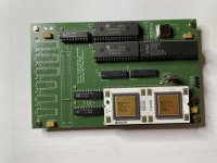
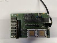
Not really satisfied with my breadboard attempt to build another PDP-11/Hack and also because I wanted to investigate a little bit more how the DCJ11 really works I decided to make another PDP-11/Hack. So I designed a Eurocard DCJ11 based Singleboard Computer. The PCBs arrived today and so nothing better then set them to use. But this time the PDP-11/Hack comes with an expansion slot. So with a proper PCB and the option to expand the SBC it has now become a "PDP11/Hack de luxe"
Here is a picture of the recently built unit
IMG_9539.jpeg
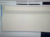
It is still a prototype and as expected already required an ECO. But not to bad for a start. If you ask what is this cable attached to the right, this is a USB to Serial/TTL adapter that connects to the console. As the complete computer draws less than 200mA the adapter also provides power via USB. And below the output of the mandatory PDP-11/Hack test program.
IMG_9541.jpeg
Sorry for the bad picture of the screenshot, but I think you get the idea. As a change of pace I used a real DC319 as the UART. The SBC only uses TH ICs. SMD parts are only used for the capacitors and resistors. Also I only used standard TTL logic. Byte writes are decoded properly, Power-Up is decoded and the 74HCT541 provides a defined power-up configuration and it comes with a reset button and a reset logic as well.

Cheers

Peter
 
Thanks for sharing!

This is very cool and def way cleaner than with the tons of jumbled wires ;-)
 
Cool stuff (y)
I have a few remarks, but maybe they are completely misplaced.
  1. I do not see a jumper to disconnect the 5V for power supply via USB. Maybe additions pop up in the future, taking the current over 500 mA. Then the USB power supply should be disconnected and ower has to be connected directly to the board.
  2. Looking at the space available on the board, why did you go for SMD resistors and capacitors? There are a lot of "old guys" in the PDP-11 community with eyesight no longer that of a youngster. IMHO, there is sufficient space for "normal" Rs and Cs (more in line with the old tech stuff).
  3. Why did you choose an card-edge type of connector? Something similar to DIN41612 (as used in VME systems) would be more reliable. Further, would it not make sense to have that connector at the edge of the board?
You probably had good reasons for the choices you made. Just curious ...
 
I do not see a jumper to disconnect the 5V for power supply via USB. Maybe additions pop up in the future, taking the current over 500 mA. Then the USB power supply should be disconnected and ower has to be connected directly to the board.
Or a diode would work without risking forgetting to remove the jumper, though you would get the voltage drop which might cause issues.

CW
 
Cool stuff (y)
I have a few remarks, but maybe they are completely misplaced.
  1. I do not see a jumper to disconnect the 5V for power supply via USB. Maybe additions pop up in the future, taking the current over 500 mA. Then the USB power supply should be disconnected and ower has to be connected directly to the board.
  2. Looking at the space available on the board, why did you go for SMD resistors and capacitors? There are a lot of "old guys" in the PDP-11 community with eyesight no longer that of a youngster. IMHO, there is sufficient space for "normal" Rs and Cs (more in line with the old tech stuff).
  3. Why did you choose an card-edge type of connector? Something similar to DIN41612 (as used in VME systems) would be more reliable. Further, would it not make sense to have that connector at the edge of the board?
You probably had good reasons for the choices you made. Just curious ...
As mentioned this is just a prototype, a draft so to speak, and it served as the learning piece for KiCad. I got impatient and wanted to get a working sample before every detail was honed to perfection. There will be a final version and more info on my homepage.
  1. Indeed, normally I put a zero Ohm resistor, but here I forgot. My bad :oops: . The final version will have a place to put a jumper/wire/resistor/diode.
  2. Here I don't agree. Being an "old guy" myself and having problems with my eyesight I'm still using a lot of SMD stuff. When it comes to 0.5mm pitch stuff I use a lamp with magnifying glass or the microscope. In my experience 0805 sized SMD resistors and capacitors are as easy to solder as TH equivalents. With TH components you always have to bend the wires and cut them later and you always need to turn around the PCB. SMD parts help you to save time. The goal was not to be in line with old tech stuff, but honestly SMD capacitors and resistors are pretty much in line with the era of the DCJ11. And in case you really have problems soldering SMD, you can always order the PCB with the SMD parts assembled. Problem solved.
  3. The card-edge decision was a cost based decision. This SBC will serve as the base for tests and experiments I have in mind. As a result there will be many expansion boards built just for the purpose to answer one or two questions I have.
Here some points from my planned to-do list
  • Use a GAL instead of the six TTL logic devices. That's the reason I did use sockets for them so I can remove them and put an expansion card with a GAL22V10 on it. I recently learned that ATF22V10C can be programmed by some cheap programmers. This is rather a nostalgic project. I used GALs some decades ago and in the last years was mostly using CPLDs, but many times a CPLD is pure overkill and the ATF22V10C has the advantage that they are available in PDIP-24 packages. And certainly matching the era of the DCJ11. The goal is to write some sort of primer in how to use GALs.
  • I'm aware that not everybody has a DC319. I only know of one offer on ebay where you can buy them and you need to buy at least a tube with 11 pieces. But in fact when you look at the price per piece they are very inexpensive. The CDP6402 and it's pin replaceable companions are much easier to get and you can buy just one. So another expansion board will use a CDP6402 and some glue logic for those that don't have DC319 but have a CDP6402.
  • For another project I need to test how the DV signal works in detail.
  • I want to fully understand power-fail
  • And then there is that piece de resistance, an expansion board that turns this SBC into a PDP-11 able to run RT-11.

I hope that explains your concerns.

Cheers

Peter
 
Peter,

Once you have all of the kinks worked out have you considered making a kit for those of us who would like to have an 11 that is a little bigger than a Pi😁.

Thanks,

Mike
 
Hi Mike,

I will certainly publish everything, but providing kits I donˋt think so ;).

Cheers

Peter
 
I was only making remarks, definitely no criticisim. I did not make a remark on those 6 TTL ICs, but I actually did think of one or two GALs replacing them :)
Might make routing simpler as well. 0805 SMD I can handle, but it's just that I prefer TH components.
Anyway, you have a cool project on your hands, and I will be following it (y)
 
No problem. As for the 6 TTL ICs, yes one GAL16V8 would easily replace them. I was in fact thinking to replace the 6 TTL ICs with a GAL16V8 for the final version. But one of the primary goal of the PDP-11/Hack is, that it can be built without the need of programming devices. So anybody with decent solder skills, a DCJ11 and a DC319 should be able to build it. I will be using GALs and CPLDs for the planned expansion cards.
 
  • Like
Reactions: cjs
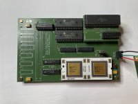
With the issue I had with the DC319 now being solved PDP-11/Hack de Luxe is taking its next step. Unfortunately the new PCB does not address the issue with the DC319 I had, but a small wire (on the back) adds the missing connection.The final version now has the option to use a GAL instead of the 6 TTL logic devices and I also made a small adapter, that plugs into the socket for the DC319 and allows it to use a CDP6402 as UART instead of the DC319.

Below is a picture using a GAL and the DC319. The layout still has the option to use 6 TTL logic devices instead of the GAL in case you don't want to use a GAL or you don't have it or can program it.

DCJ11-SBC-PCB-V1-3-GAL.jpeg

The CDP6402 adapter however requires a GAL, sort of contradictionary, but this is rather a proof of concept. A solution using three TTL logic devices is on it's way. It will use SMD parts, but the KiCad project will allow you to order adapters with the SMD parts already mounted. So this should definitively not be the issue. Here you can see how the adapter is used
CDP6402-MINI-Installed.jpeg
As you can see I did not yet install the card edge slot. Just a solder bridge between !CONT and !SCTL makes sure the write cycles are stretched enough to make the UART happy even when running the DCJ11 with a 20Mhz crystal or faster. I already started with the documentation and will make it available via my home page where you also will be able to download the KiCad projects.
 
This is very clever. Perhaps a barebones kit could include a PCB and list of parts. I would be interested :-)
 
Many thanks, Peter, for your documentation, it will give me the opportunity to reflect for many hours on this or that behavior of the J-11
 
Hans Hübner the owner of the mysterious ISA card with a DCJ11 asked me whether I was willing to send him one of my spare PCBs to build as well a PDP-11/Hack de Luxe as he wanted to make good use of his DCJ11. The ISA card also had a DC319, so he was soon up and running as well.
His intention was to load a standalone Forth and soon he managed to load a Forth stand-alone binary via the console. But thats when things really started. Stand alone Forth exists for RX01 and RL02 and Stackosaurus has an excellent site describing in full details how to create stand-alone Forth for RX01 and RL02. As the PDP-11/Hack de Luxe will never be able to do DMA soon the idea came up to use another serial interface and a TU-58 emulation as the mass storage for a stand-alone Forth. Hans soon had a development environment ready and based on his work I started to develop TU-58 IO routines that could be integrated into a stand-alone Forth.

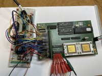
First I needed to get this second serial interface. Good thing the breadboard interface expansion cards had arrived and soon I whipped up a second serial interface on a breadboard

IMG_9595.jpeg

The things that needed to be developed where a BOOTSRAP loader, a BOOTLOADER and the IO routines for Forth that would replace the stand-alone routines for RX01 or RL02. Because of some constraints at the beginning of the hardware design I was looking for a short DD bootstrap loader that would fit within 32 words. In the meantime several solutions to this problem are known, but also the constraint no longer exists, and I learned a lot about the TU-58 protocol. Finally all three routines have been written and combined into a single TU-58 disk image that can be booted on the PDP-11/Hack de Luxe. And here we go: Forth on the PDP-11/Hack de Luxe booting from TU-58.

Code:
@140000g
FIG-FORTH  V 1.3.3
  OK
1 load
LOADING EDITOR... R ISN'T UNIQUE I ISN'T UNIQUE
LOADING ASSEMBLER... R0 ISN'T UNIQUE # ISN'T UNIQUE
LOADING STRING PACKAGE...
LOADING STRING EXTENSIONS...
BYE ISN'T UNIQUE
 OK
vlist 
DLIST   MOVE   BYE   DUMP   DUMPCELL   6Z#   ULIMIT   ADDR+   LOWADDR   
HIGHADDR   ASCII.   RAD50.   RADIX50   RADASCII   ASCIIRAD   MSB   
LSB   ><   $+   $+-EVEN   $>   $=   $<   $COMP   TEMP   $SWAP   MOVEW   
$OVER   $SECOND   $VAL   $STR   $SEG   $DUP   $VARIABLE   $DIM   
$!   "   $NULL   (")   $@   $@TEXT   $?OVER   $.   $COUNT   $DROP   
$LEN   $CLEAR   $SP   STACKSIZE   CODE   ENTERCODE   OLDBASE   ASSEMBLER   
SCREENMOVE   EDIT   E   #ARGS   STK   STACKPTR   CURSOR   ESCR   
EDITOR   TASK   FORTH   ;CODE   R/W   DDWR   DDRD   BYE   VLIST   
TRIAD   INDEX   LIST   U.   ?   .   D.   .R   D.R   #S   #   SIGN   
#>   <#   SPACES   WHILE   ELSE   IF   REPEAT   AGAIN   END   UNTIL   
+LOOP   LOOP   DO   THEN   ENDIF   BEGIN   BACK   FORGET   '   -->   
LOAD   MESSAGE   .LINE   (LINE)   BLOCK   BUFFER   DR1   DR0   FLUSH   
EMPTY-BUFFERS   UPDATE   +BUF   M/MOD   */   */MOD   MOD   /   /MOD   
*   M/   M*   MAX   MIN   DABS   ABS   S->D   COLD   NOT   ABORT   
QUIT   (   DEFINITIONS   VOCABULARY   IMMEDIATE   INTERPRET   ?STACK   
D<   U<   DLITERAL   LITERAL   [COMPILE]   CREATE   ID.   ERROR   
(ABORT)   UPPER   -FIND   NUMBER   (NUMBER)   WORD   PAD   HOLD   
BLANKS   ERASE   FILL      QUERY   EXPECT   ?ALIGN   ."   (.")   
-TRAILING   =CELLS   TYPE   COUNT   DOES>   <BUILDS   (;CODE)   OCTAL   
DECIMAL   HEX   SMUDGE   ]   [   COMPILE   ?LOADING   ?CSP   ?PAIRS   
?EXEC   ?COMP   ?ERROR   !CSP   PFA   NFA   CFA   LFA   LATEST   
TRAVERSE   -DUP   SPACE   ROT   >   <   =   D+-   +-   -   ,   ALLOT   
HERE   2-   1-   2+   1+   PREV   USE   HLD   R#   CSP   FLD   DPL   
BASE   STATE   CURRENT   CONTEXT   OFFSET   SCR   OUT   IN   BLK   
LIMIT   FIRST   VOC-LINK   DP   FENCE   WARNING   WIDTH   TIB   R0   
S0   +ORIGIN   B/SCR   B/BUF   C/L   BL   3   2   1   0   USER   
VARIABLE   CONSTANT   ;   :   C!   !   C@   @   TOGGLE   +!   DUP   
SWAP   DROP   OVER   DMINUS   MINUS   D+   +   0>   0<   0=   R   
R>   >R   LEAVE   ;S   RP!   SP!   SP@   XOR   OR   AND   U/   U*   
CMOVE   CR   ?TERMINAL   KEY   EMIT   ENCLOSE   (FIND)   DIGIT   
I   (DO)   (+LOOP)   (LOOP)   0BRANCH   BRANCH   EXECUTE   LIT    OK

Currently I do not have the BOOTROM implemented on the breadboard, so I have loaded the BOOTSTRAP loader at address 140000 (via ODT :)), this will load the BOOTLOADER from Block 0 (what else) and the BOOTLOADER will load FORTH.BIN into memory and start it. Forth only uses the first 32kbyte of memory, so the bootstrap code is save as long as I do not power-cycle the PDP-11. I have integrated the FORTH.DAT from the RX01 standalone Disk into the TU-58 image. For the moment the Forth with stand-alone TU-58 IO routines is not part of FORTH.DAT as it should be, but I'm working on it. Anyhow for first tests this works well. The software is of course still in beta phase, but the biggest problem is, I have almost no Forth skills. Now I will have to learn Forth.

Peter
 
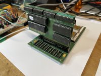
Here an update to the DCJ11 SBC Projekt. I have now finished the Multi IO Card, this card implements a second serial interface, a Boot ROM and features a W65C22S VIA to give the DCJ11 SBC some GPIOs. As you can see the connectors are still missing, they were unfortunately out of my home stock.
IMG_9639.jpeg

As you can see the second serial interface uses a CDP6402 which is easier to get and the common UART for PDP-11/Hacks. However in this setup the interface is used to connect to a TU-58 emulator. The Boot ROM hosts a small Bootstrap loader for TU-58. I did not jumper the power-up code, so I still have to enter a 173000g to get into Forth

Code:
@17773000/012703
17773002/176504
17773004/010301
17773006/005213
17773010/012702
@173000g
FIG-FORTH  V 1.3.3
1 list
SCR # 1
  0 ( LOAD SCREEN)
  1 DECIMAL
  2 1 WARNING ! ( GET ERR MSGS, NOT #S)
  3
  4 CR ." LOADING EDITOR... "  6 LOAD 7 LOAD 8 LOAD 9 LOAD
  5 CR ." LOADING ASSEMBLER... "  10 LOAD 11 LOAD 12 LOAD 13 LOAD
  6          14 LOAD 15 LOAD
  7 CR ." LOADING STRING PACKAGE... "  19 LOAD 20 LOAD 21 LOAD
  8          22 LOAD
  9 CR ." LOADING STRING EXTENSIONS... " 18 LOAD 23 LOAD
 10 CR
 11 : BYE FLUSH CR ." LEAVING FORTH.  HAVE A GOOD DAY." CR BYE ;
 12 CR
 13
 14
 15 -->  ( CONTINUE ON NEXT SCREEN )
 OK

Documentation is still on-going, but quite advanced, so you can expect the full description in the next few days here DCJ11 SBC.

Peter
 
Back
Top