• Please review our updated Terms and Rules here

PDP-9 at the RICM

I bet those are white cards just like yours, but the light is reflecting differently.

It could be. The W103 is a PDP-9 I/O Address Decoder. There should be three of them in the chassis.

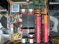
Maybe czunit chassis is missing a few Flipchips? Sorry the picture came from another collector and I don't have a better one.

The RICM has an AF01 in the warehouse from a PDP-8. I can get a picture of the inside of that for comparison.
 
That would help. This one came from a pdp12 system oh.... 37 years ago now. I couldn't save the 12 (far too big to put in a station wagon) but I did save the 64 bit FPP12 and this AF01.

And here, as they say, it is.
CZ
 
That would help. This one came from a pdp12 system oh.... 37 years ago now. I couldn't save the 12 (far too big to put in a station wagon) but I did save the 64 bit FPP12 and this AF01.

And here, as they say, it is.
CZ
I thought that the W103 Address Decoder was PDP-9 specific. I wonder how that flipchip works with the PDP-12?
 
I thought that the W103 Address Decoder was PDP-9 specific. I wonder how that flipchip works with the PDP-12?
From page 142 of the 1967 logic handbook. The W103 is listed as PDP-8 Device Selector. It is used to decode the six device selector bits. In that manual they called it the PDP-8/S I/O bus which we would read today as specifically for the S but they meant both the PDP-8 and the PDP-8S models. Today we would use the term Negibus but that doesn't seem to exist until they needed a distinction between the older I/O bus and the Posibus. This card is found in any Negibus peripheral device and the Straight 8, 8/S, LINC-8, PDP-9, and probably some machines I cant think of right now. They would not be found in Posibus machines, but in any attached Negibus peripherals they would be probably be present. The 1967 list price was $52 which adjusted for inflation would be $477 in 2023. I probably have half a dozen of these new in bag that still have all their diodes intact. You would select the device code by clipping the appropriate diodes.

The PDP-12 should have these only if there were a Posibus to Negibus converter and then some Negibus devices attached. It may be that because of the standard peripherals they all had these. I can look at Vince's 12 next week. I know that the early PDP-8/I's had Negibus but I always assumed that was because there were no posibus peripherals yet and they came with the converter.

I have an AF01 and the manuals for it. I have not powered it up for over 20 years but it worked then. It is mounted in the cabinet to the right of my Straight 8 CPU. It was used from 1967 through 1972 by the Institute for Atmospheric Sciences in thunderstorm research.

The AF01 had several options one of which was extra MUX inputs. You could equip them with up to 64 inputs. I believe mine only was equipped for six. It could also have a sample and hold board installed which mine did not have. And the other optional board was an amplifier which could adjust the input levels to give you the 10 volt swing of the AF01 inputs. I have since found some of these cards on Ebay but have not put them in the AF01. I briefly used it to monitor battery discharge curves. But while running the 8 for hours in my basement in the winter was fine, in the summer not so much.
 
Thanks Doug, I never considered that I might be able to use PDP-8 Negibus peripherals on a PDP-9.
 

Attachments

  • 1692116021280.png
    1692116021280.png
    27.6 KB · Views: 5
Correct. It's also single-sided negibus, as I think there was also double sided negibus and of course Posibus. My 8 had a DW08 positive to negitive adapter. Or was it a negitive to positive bus adapter. Might have been the latter, as the paper tape controller was an external device and was most likely negibus but the RK8 was most definitely posibus as was the FPP12.

There were.... a lot of wires.... connecting everything. But if you could take a picture of your system Doug I'd appreciate it as I wonder which cards go where these days.
 
And of course the ribbon cable posibus vs the coax posibus. Simplicity at its finest.
 
Thanks Doug. With the exception of my R107 being one slot up (maybe a mistake on my part) and my extra multiplexer cards, these are identical.

Good to know. Now I need to do something with it......
 
Thanks Doug. With the exception of my R107 being one slot up (maybe a mistake on my part) and my extra multiplexer cards, these are identical.

Good to know. Now I need to do something with it......
Glad I could help.

Without the sample and hold card you will need to convert voltages that do not change during the course of the conversion or at least don't change much. I was tickled to find what I was thinking would be impossible to find cards on Ebay a number of years ago.

I was wrong about the number of mux inputs my machine was equipped with. It appears to be three cards each with four inputs making it have twelve.
 
Looks like the two PDP-9 I/O cables plug into slots CD15-CD16 and CD17-CD18 or slots CD19-CD20 and CD21-CD22.
Now I need to look at the AF01 that is in the RICM warehouse.
 
I would guess that is the Negibus in and out. Not sure which is which (or if it matters). I forget, did we put terminators on the last device on a posi or neigbus?
 
I would guess that is the Negibus in and out. Not sure which is which (or if it matters). I forget, did we put terminators on the last device on a posi or neigbus?
There's a Gxxx card for that. It has a few 100 ohm resistors to ground IIRC terminate the timing/contol lines.
 
I would guess that is the Negibus in and out. Not sure which is which (or if it matters). I forget, did we put terminators on the last device on a posi or neigbus?
It doesn't matter which connector set is used for in and out. The PDP-9 manuals show the tradition is the upper connectors are in, and the lower connectors are out. There are some exceptions when the connector slots are side-by-side.

You can also see that the I/O bus is 18-bits on those slots.
 
Still chasing memory errors when running the Memory Checkerboard diagnostic. At least now it is only on bit-7. I have swapped lots of Flipchips for bit-7, but haven't found the culprit yet.
 
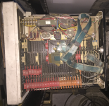
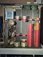
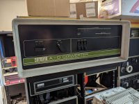
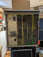
I found the two AF01 chassis in the RICM warehouse. One has no flipchips at all. This one is very different than the layout that 1944GPW posted.

1693092293936.png
 
Hm. I'll have to compare that to mine (which matches the other one). Interesting that you don't have the high precision reference voltage supply, I wonder if that was just an option or something as the one on Ebay didn't have it either.
 
PXL_20230827_182149749.jpgPXL_20230827_182306002.jpgPXL_20230827_182339359.jpg

Here are photos of my unit for further comparison. I've not looked into cabling it up or powering it on, and have no idea yet if I have a complete-ish set of Flip-Chips for it.
 
Back
Top