• Please review our updated Terms and Rules here

PDP-9 at the RICM

We are getting closer to the cause of the clock data-break problem. When a data-break from the clock is granted, a bit in the microcode gates the Word Count address from the I/O controller to the O bus in the processor. This part is working reliably. There is complex circuitry combined with microcode bits that then gates the Word Count address from the O bus into the Memory Buffer register. This sometimes works OK, sometimes it doesn't. That would make the data-break increment the wrong Word Count address in memory, and cause the clock to work erratically.

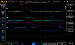
In the first 'scope image below trace 1 is the EXT(1) microcode bit that gates the data-break address onto the O bus. Trace 2 is one of the data-break address bits on the O bus. Trace 3 is the corresponding bit in the MB register. Trace 4 is the MBI(1) microcode bit that actually gets set by complex circuitry. When trace 4 goes low coincident with trace 2, the data bit gets latched into the MB.
1667744452909.png

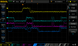
As shown below sometimes the MB(1) bit doesn't get set, and the data-break address doesn't get latched into the MB. Since this is a very asynchronous machine, there are 6 B310 adjustable delay lines in some really complex Control Memory timing circuitry that eventually should set the MB(1) bit. If the cumulative delay is off by 25 ns or so, the AND gating logic doesn't work and MB(1) won't get set. You will also artifacts where signals get enabled for a short time when they shouldn't. That is probably what is making the spikes on traces 2 & 3.
1667743959451.png

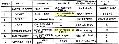
What we need to do now is check the Control Memory timing adjustments, and look for jitter on any of the clock signals. There are wire-wrap jumpers on the processor backplane that can be changed to adjust the timing of each delay.
1667745253576.png


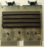
I think that we have something in the clock circuitry that is intermittent and is causing jitter in the clock signals. We have had this problem before with the B310 flipchips shown below. The long black devices are inductive delay lines. They have 5 wires on the back soldered to the PCB. Because of the difference in thermal expansion between the delay line and the PCB the solder joints crack and go intermittent. The newer versions of the N310 have the delay lines rotated 90 degrees to the PCB so there is some wire between the delay line and the PCB that can flex and absorb the thermal expansion. We don't have enough of the newer B310 modules to replace them all. We could also have a failing transistor on one of the delay lines, or elsewhere in the CM timing circuitry that is causing the jitter.
1667746159356.png
 
Some success with the PDP-9 yesterday. I went through the Control Memory (Microcode) timing checks in the System Adjustment Manual. To change the CM timing you need to unwrap and rewrap wires on the backplane to configure delay lines. This was done at the factory when the machine was built, and the configuration in the schematics may not match a particular machine due to manufacturing tolerances. The timing was close enough, so I left it alone.

I looked at the I/O Adjustments because that seems to be where the problem is. When an I/O instruction is executed there are three microcode words that are executed, and then control is transferred to the I/O controller. When the I/O controller is done it sends an I/O Restart signal to the processor, and it starts executing microcode words again. We replaced a broken delay line in the I/O controller a few weeks ago, and adjusted the delay to the 500 ns that is listed in the schematics. When we checked the I/O Restart signal according to the procedure in the System Adjustment Manual, the signal looked just like the image for "I/O Restart, Incorrect Set Up". Apparently the Microcode will stop when waiting for a core memory cycle to complete, or when an IOT instruction is being executed. The delays for both need to be exactly the same. We adjusted the I/O Restart signal delay trimpot until the memory and I/O delays were the same.

Now the clock and it's partial data-break cycle is behaving again. Instruction Test #2 that tests I/O, Clock, and Interrupts runs OK.

We loaded the diags for the 1/2" mag tape controller so we can run the data-break tests, and it failed miserably. We have successfully run this diag before, so I know that it works. The diag documentation that we have is for the PDP-9, and the diag paper tape that we have is from a PDP-15. That makes it challenging to localize any failures. I wrote a PDP-9 diag disassembler so I have a start at the source code for the PDP-15 version of the diag. The PDP-15 version is not too different from the PDP-9 version so I should be able to add comments from the PDP-9 version to the disassembled PDP-15 version to reproduce the original source code.

Tomorrow we will work on the 1/2" mag tape controller.
 
Of course the 1/2" mag tape controller is misbehaving now. We can write to the Command Register, but cannot read it. The possibilities are the processor, I/O controller, cables, or the TC59 tape controller. This shouldn't be to difficult to fix.
 
We toggled in a two instruction program to read the TC-59 Data Register and then jump .-1, and then used the 'scope to to trace TC-59 Data Register data from the controller, to the I/O cables, to the cables that connect the I/O controller to the processor, to the I/O Bus to O Bus multiplexor, to the AC Register. We found a problem to the LIO signal that gates the I/O bus onto the O bus. The O bus to AC register ACI signal looks OK. The LIO signal has two pulses when it should have just one. The first pulse loads the data from the TC-59 into the AC, and then 1 uS later the second pulse loads zeros into the AC because the I/O bus has been deactivated by then. We have seen this two pulse issue before in other parts of the machine when delay lines are not adjusted correctly. A few weeks ago we adjusted an I/O Controller delay line to get the RCT working. I really hope that we don't end up in a conflict with the optimal delay line settings for the RTC and the external controllers.

After running the two instruction program for a few the processor could not read the Command Register in the TC-59. Maybe accessing the TC-59 every 5 uS warmed up a component so that it misbehaved?
 
I spent Wednesday chasing the data and strobes that move the TC-59 Data Register to the I/O Bus to the O Bus to the AC. The first ACI and LIO pulses worked correctly and the data was loaded into the AC. Just 1 uS later there was another ACI and LIO pulse, but the I/O bus was not being driven at the time so zeros were loaded into the AC.

In the PDP-9 the peripheral controller sends a RD REQ signal to the I/O controller and processor to indicate that the I/O bus is being driven and it is OK to latch the data into the AC. On the TC-59 this signal is always active. We tried swapping the R123 flipchips that drive this signal, but there was no change. I need to make sure that the -15V is present on the R123 flipchips.
 
We chased the RD RQ in the TC-59 and found a W640 pulse amplifier that was not working and replaced it with a spare. There are five connections to this signal that we could find on the TC-59 schematic. One for the cable to the processor, and four for read, write, status, and control gates to the I/O bus. We pulled all of the flipchips and the cable that drive the RD RQ signal and measured its resistance to ground. It was more than 200 megOhms, so no other flipchips were connected to the signal. We measured the voltage on the RD RQ signal and the RD RQ signal stayed active at ground. We added a 10k Ohm resistor to -15V and the signal went to -15V. We added the connected devices one at a time and the voltage went to -5V because one of the Flipchips has diode clamps on it. Of course we did this by powering off adding the device, and powering it back on. We ran the TC-59 diags and it passed the IOT, Command Register, and Data Buffer diagnostics. Now we know what the problem is with the RD RQ signal.

After looking at the I/O controller schematics we can see that there are three pull-down resistors on the RD RQ signal on two W005 Flipchips. The W005 has a 3k Ohm pull-down to -15V and a diode clamp to -3V. I suspect we have another power problem where -15 is not getting to slots H19 and F17. They are both feed from the #5 margin switches and the same fuse, so we know where to look.
 
Mode progress with the PDP-9. The chassis covers the whole rear door and has 36 switched to select between constant +10V & -15V and the variable margin power supplies. It has a total of 72 telephone type indicating fuses for power to the Flipchips. We wiggled all of the fuses and operated all of the margin switches. The -15 is back to the W005 terminator Flipchips and the RD RQ signal on the I/O bus has a pull-down to the inactive state.

We had hoped that fixing the power problem would fix the Data-Break problem, but no such luck. We did some debugging for why the processor runs part of the TC-59 diagnostic and then hangs, and found that the BK SYNC signal was always on when it hung. This causes the processor to start with Control Word 11 and execute the Data-Break microcode instead of starting with Control Word 10 and executing an instruction. This causes the processor to constantly execute Data-Breaks instead of instructions.

The really curious this is that when running test #3 in the TC-59 diagnostic the processor runs lots of instructions and does exactly 23 single-cycle Data-Breaks and then hangs. This is very repeatable, so there is some specific test case that causes the hanging. I will have to improve my PDP-9 disassembler to be able to find out exactly what the diagnostic is testing when it hangs.
 
I fixed the bugs in my PDP-9 paper tape disassembler so I have source code for the TC-59 Maindec. It does a XCT DSCOPE before and after each test. The XCT instruction executes the instruction at DSCOPE which normally contains a CLL instruction. I changed it to a HLT instruction and now I can run the individual Date-Break tests and see the outcome. The TC-59 Read, Read/Compare, Space Forward, and Space Reverse instructions all work OK. The TC-59 Write instruction puts the processor into a microcode loop where it constantly executes Da-Break and no instructions.

It looks like transferring data from the peripheral controller the I/O Controller and into the AC, and incrementing the MB works OK. As soon as it tries to transfer the AC through the I/O Controller to the peripheral controller the processor hangs. With this information I can look for the specific signals on the TC-59 and in the I/O Controller that handle the I/O Writes and hopefully find what is broken.
 
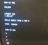
We found a broken S107 Inverter Fipchip that prevented the WR RQ signal from the TC02 or TC59 from turning into the WR RQ(B)\ signal which prevented the DCH SYNC flip-flop from being cleared which caused the microcode to always run Data-Break cycles instead of instructions when you tried to read from the peripheral. It booted ADSS V5 from DECtape. What a struggle to fix this.

ADSS Hello World.jpg
 
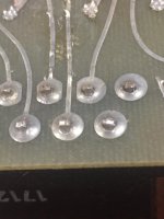
The #6 lamp in the register display has been intermittent for years. Saturday removed the board that holds all of the lamps to fix the problem. The lamps in the PDP-9 have no pins or sockets, just bare wires soldered into the PCB. I was really afraid that we were going to damage other lamps in the process. We connected a current-limited power supply to the lamp board with the connections backwards from normal. This will cause all of the switch transistors to turn on, and light all of the lamps. All worked! We closely inspected the PCB and solder joints, and found black rings around several connector pins, including the pin for lamp #6. We removed the old solder, cleaned the plated-through hold and connector pin, and resoldered the connections. After very careful reinstallation we were rewarded with all working lamps except for "DATA".

The data lamp is supposed to illuminate when a data-break is in progress. The schematic says that the signal that turns on the lamp should be on for 100 us. We checked the wiring, and it is correct. The way it is wired the signal should only be on for 40 us, and it is. We need to insure that the signal is getting to the switch transistor on the lamp board, and if it is, try lengthening the on-time for the signal.

We also found that the right reel motor for one of the TU55 drives is not working again. We will inspect that Wednesday.

Bad Solder Connections.JPG
 
Our latest issue looks like a thermal problem with memory. When you first turn the machine on, it will not boot ADSS. It passes Instruction Test #1, but Instruction Test #2 fails when it does an indirect XOR with auto-increment. It drops bit #3 every time, until it warms up for about 20 minutes. On Wednesday I will try memory swapping boards that are related to bit #3 and see if the issue moves.
 
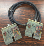
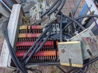
I bought another 7 foot long BC09 cable in eBay, identical to the one that Bill Degnan donated. I can now connect the processor to the TC02 DECtape controller with the correct cables. I also bought 1/2 of a cut BC09 cable. I am in the process of making CAD files for the W850 boards on the ends of the cable so I can make two 3 foot long cables to connect the TC02 to the TC59 Magnetic Tape controller. I will need another pair of BC08 cables, or something similar, if I ever get to making a disk emulator for the PDP-9.
 
It turned out to be three unrelated failures occurring at the same time.

The PDP-9 is running OK now. I still need to fix one TU55 motor drive board. I am having difficulties repairing any of the three broken ones that we have.

The PDP-12 had a serial console problem that was fixed by wiggling the flipchips that make up the console UART. It ran fine for a few days. Yesterday I was copying files from an RK05 disk image to the physical RK05 disk and the processor died. I can load a diagnostic using the BIN loader, and the BIN loader halts with the AC cleared and the LINK on, so it loaded OK. When I run the diag I see memory bits in the code that are dropped. This may be a core memory problem. I will work on this tomorrow.

The PDP-8/I issue turned out to be a broken wire in the console cable to the Teletype, so that was an easy fix.
 
Back
Top