• Please review our updated Terms and Rules here

Pensee Pascal Micro Engine WD9000

spiceminer

Experienced Member
Joined
Mar 8, 2014
Messages
205
Location
Europe
mekl.jpgmeinekl.jpg

Hi everybody!

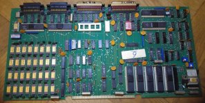
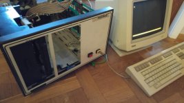
I recently have acquired a Pascal Micro Engine with WD9000 Rev E from the French company "Pensee", model PME-FKSSD, SN 01000. The unit has an inventory sticker from the public library of the city of Bonn, the former West German capital, on it.

The very sturdy and heavy box is equipped with 2 SSSD 8" Floppy drives from REMEX, type RFD 2000 and a huge power supply.

All chips (from 1979 to -80) are included, except for the WD2083U interrupt priority encoder and the 8255 Parallel I/O controller (which I assume are both optional).

I have another WD9000 Board (with the IRQ encoder installed) from the collection of a friend for reference measurements (unfortunately its working state is unknown).

Unfortunately, the Micro Engine is not working at all. The power supply is fine, but no output on the terminal port and no reaction on the floppy drives (My good friend, user "fritzeflink" was so kind to copy the images from bitsaver for me on real diskettes).

Does anybody has an idea what could be wrong here? Does anybody have experience in repairing WD9000 boards? Or knows what a healty machine does on power up? Is there a boot message for example? Anything that could be measured (like reset signal)?

Best regards
Stephan
 
Last edited:
Nice!

I have been looking for a WD9000 for a while myself...

Firstly, have you found the 'mega documentation stash' over at http://bitsavers.trailing-edge.com/pdf/westernDigital/WD90_Pascal_Microengine/?

In particular http://bitsavers.trailing-edge.com/...croengine/Pascal_MICROENGINE_RefMan_Mar79.pdf.

Slightly different packaging - but what appears to be the same board.

The documentation says to power up the machine, insert the system disk and press RESET. The system should announce itself and you should be presented with the menu.

For the system to BOOT - you should see the disk drive select light turn ON.

If this doesn't happen, I would suggest documenting all of the switches on the main board and I will see what they do (as you have them configured).

EDIT1: After looking at the schematics I believe the 8255 should be fitted (although it probably won't make much difference if it isn't) - but I would like to bet that the interrupt priority encoder IS required (it handles the serial interrupts). I will have a hunt a bit further for you...

EDIT2: Yes, there are reset and clock signals. First of all, check the power supply rails are correct. The power on reset capacitor is C33 (33 uF). The RESET signal should be present on X9 (74LS04) pin 8. The /RESET signal (yes, there are two of them) should be present on X9 (74LS04) pin 6. Use a multimeter or oscilloscope and depress the RESET button to test the signal. The next thing would be the clock(s). The clock is generated by E1 (2143) and divided down to produce sub-clocks by E2 (3245). I would next check X17. This device produces the serial clocks. Any of these devices failing would result in nothing being observed!

EDIT3: Correction. I see memory address FC4x is 'reserved' for the Interrupt priority latch - so this may not necessarily be fitted. HOWEVER, the same document then goes on to describe that the devices require the use of the interrupts???

I see you have the dreaded 4116 DRAMS fitted. Gut feeling tells me that some of these will have gone...

Dave
 
Last edited:
Earlier versions of the MicroEngine do not have the interrupt encoder, and do not need them . Later version have them and require them.
The OS is not compatible between them, so make sure you have the right images.
Stephan has the earliest version and does not need this chip.
Mine needs to be fired up, alas too many projects running. A couple of ICL1501 and Philips P854 machines have found refuge with me.....

EDIT : AFAIK the bitsaver images are for the later variant and will not work on this earlier board. Still need to image my disks, as they are for the earlier variant.

Jos
 
Last edited:
That probably clears up the interrupt encoder Jos - it depends :)...

You may need the RTS/CTS and DTR/DSR lines to be connected together - or connected to the correct lines on your terminal - for the serial port lines (specially Port A (J1) system port) to work.

I can just make out the orientation of the switches and can see that 8" SD is set (which matches what you physically have). I can't quite work out which switches are OPEN and CLOSED on the serial port configuration switches though. It doesn't quite look 'standard' to me - but then standard may not be standard depending open whether the documentation I have refers to a early or late version.

Some close-up photographs of the switches may help.

Dave
 
Not yet. JDreesen promised to provide a copy of the Operating system to me that matches my machine. In addition, I had no spare time yet to check the suggestions you made (which are highly appreciated!). But I hope I will manage it to bring the boards back to the surgical table soon.
 
Back
Top