• Please review our updated Terms and Rules here

Philips :YES

No. Often for a single card, it is not done. It likely expects multiple cards.
It might need a change of the address mux as well. I know that for the Olivetti M20 it requires changes at the address mux. Ir does 256k without any change but needs different addresses at the mux.
Dwight
 
Hi,

I can now report success.

Jumper bridge J5 next to IC 7003 (type 74F14N) selects between "128k" (bottom) and "512k" (top). After replacing the 4164 chips with 41256 chips, this bridge needs to be moved to detect 512 KB of memory. After tracing a rather large amount of circuitry on the board, I also found two AMPAL16R6DC, of which one is related to DRAM address decoding.

With graphics mode disabled, chkdsk now shows 632 KB total memory:
Code:
A>chkdsk

    728064 bytes total disk space
     38912 bytes in 2 hidden files
     58368 bytes in 8 user files
    630784 bytes available on disk

    647168 bytes total memory
    604160 bytes free

When graphics mode enabled, chkdsk reports 575 KB total memory:
Code:
A>chkdsk
    ...
    588800 bytes total memory
    540928 bytes free

Best Regards,
Svenska
 
Hi,

the success I reported was too early, and I apologize for the misinformation. The BIOS does not actually test memory at boot and since most of the software provided with the system works fine in a 128 KB configuration, memory above 256 KB is rarely accessed. I wrote a small memory test program in assembly language to verify this.

In any case, the solder bridge J5 can be switched between "128k" and "512k" and will only affect the amount of memory seen by the system. Trying to access memory beyond 256 KB will hang the system. When using 41256 DRAM chips, the solder bridge J3 (labelled MEM SEL) needs to be moved towards the connector as well.

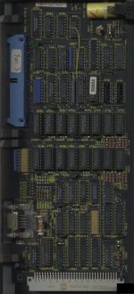
In the attached picture, solder bridge J5 is in the bottom center/left, while J3 is in the bottom right.

Note that overwriting the beginning of physical memory will freeze the system, even when interrupts are disabled. Some BIOS interrupts, notably int 10h, will happily enable interrupts and the next timer interrupt will crash the system if the vectors have been overwritten. Touching the end of physical memory will cause the screen show interesting corruption and freeze the system as well. It appears that not only VRAM is located in this area, but also some vital information for the graphics subsystem.

expansion-card.jpg - Philips :YES expansion card

Best Regards,
Svenska
 
Hello again,

after the PSU blew a RIFA cap, I opened the machine again and used the opportunity to read out all three ROM chips on the main board.

The BIOS ROMS are "(c) 1984 Digital Research, INC." and the files YES_23484.BIN and YES_23494.BIN contain the even/odd bytes.
The font ROM is "(c) PHILIPS 1984" and contained in YES_23494.BIN.
Also included in the ZIP file are pictures of the ROMs, showing both the copyrights and the numbers.

Best Regards,
Svenska
 

Attachments

  • yes_roms.zip
    177 KB · Views: 8
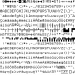
Interesting font ROM -- there are two font sizes (8x10 and 8x8) but they're not using the same codepage. And the second font begins with what look like teletext graphics.

yes_font.png - Philips :YES font ROM
 
Back
Top